
Multiscale all-soft electronic devices and circuits based on liquid metal

a liquid metal, electronic device technology, applied in the direction of photomechanical equipment, instruments, conductors/cables, etc., can solve the problems of inability to fabricate such soft and stretchable electronic devices with submicron-scale resolution, existing processes have difficulty making wires with a width greater than 500 m, and existing processes are not suitable for such soft and stretchable electronic devices

Active Publication Date: 2020-11-19
GEORGIA TECH RES CORP
View PDF0 Cites 2 Cited by
  • Summary
  • Abstract
  • Description
  • Claims
  • Application Information

AI Technical Summary

Benefits of technology

The present invention provides a method for making a flexible electrical element and a flexible electrical conductor that can conduct electricity while at a normal operating temperature. The method involves creating a stamp or mask layer with a shape that matches the desired flexible element or conductor, applying a liquid phase conductor to the stamp, dissolving the mask layer with a solvent to create a shaped liquid phase conductor, and sealing it into a primary elastomer layer. This primary layer is then applied to a substrate and an secondary elastomer layer is added to seal the conductor. The invention also includes creating an electronic element that includes a channel filled with a liquid phase conductor. The technical effects of this innovation include creating flexible electrical elements and conductors that can better conduct electricity, and provide improved performance and reliability.

Problems solved by technology

Existing fabrication technologies, including the transfer printing of compliant solid metal patterns, nanoprinting, direct printing of nanomaterials, and EGaIn patterning, are currently not suitable to fabricate such soft and stretchable electronic devices with submicron-scale resolution.
Unfortunately, existing processes have difficulty making wires that have a width greater than 500 μm.

Method used


Image

  • Multiscale all-soft electronic devices and circuits based on liquid metal
  • Multiscale all-soft electronic devices and circuits based on liquid metal
  • Multiscale all-soft electronic devices and circuits based on liquid metal

Examples


Embodiment Construction

[0018]A preferred embodiment of the invention is now described in detail. Referring to the drawings, like numbers indicate like parts throughout the views. Unless otherwise specifically indicated in the disclosure that follows, the drawings are not necessarily drawn to scale. The present disclosure should in no way be limited to the exemplary implementations and techniques illustrated in the drawings and described below. As used in the description herein and throughout the claims, the following terms take the meanings explicitly associated herein, unless the context clearly dictates otherwise: the meaning of “a,”“an,” and “the” includes plural reference, the meaning of “in” includes “in” and “on.”

[0019]Parylene is a common name for a variety of chemical vapor deposited poly(p-xylylene) polymers.

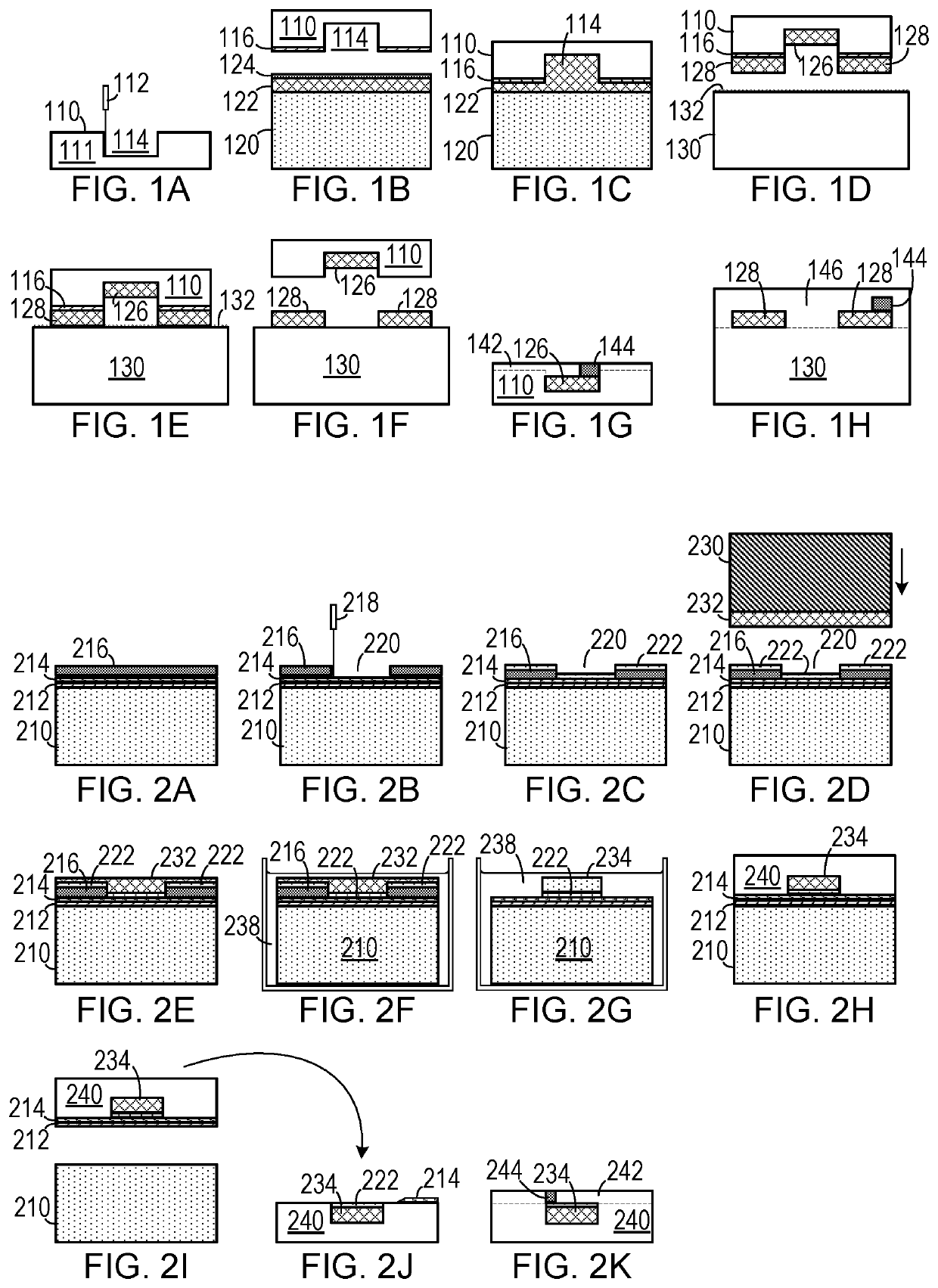
[0020]As shown in FIGS. 1A-1H, in one embodiment of a method of making a flexible electrical element that is configured to conduct electricity while at a normal operating temperature, materia...


PUM

PropertyMeasurementUnit
widthaaaaaaaaaa
diameteraaaaaaaaaa
thicknessaaaaaaaaaa

Abstract

In a method making a flexible electrical conductor, a mask layer (216) is applied to a substrate (210). A portion of the mask layer (216) is removed to expose the substrate (210) in an exposed shape (220) corresponding to the conductor. A liquid phase conductor (232) is applied to the portion of the substrate (210). The mask layer (216) is dissolved with a solvent (238) to leave a shaped liquid phase conductor (234) corresponding to the exposed shape on the substrate (210). A primary elastomer layer (240) is applied onto the substrate (210) and the shaped liquid phase conductor (234). The primary elastomer layer (240) and the shaped liquid phase conductor (234) are removed from the substrate (210). A secondary elastomer layer (242) is applied to the shaped liquid phase conductor (234) and the primary elastomer layer (240) to seal the shaped liquid phase conductor (234) therein.

Description

CROSS-REFERENCE TO RELATED APPLICATION(S)[0001]This application claims the benefit of U.S. Provisional Patent Application Ser. No. 62 / 849,372, filed May 17, 2019; this application also claims the benefit of U.S. Provisional Patent Application Ser. No. 62 / 864,571, filed Jun. 21, 2019, the entirety of each of which is hereby incorporated herein by reference.STATEMENT OF GOVERNMENT SUPPORT[0002]This invention was made with government support under 1542174, awarded by the National Science Foundation. The government has certain rights in the invention.BACKGROUND OF THE INVENTION1. Field of the Invention[0003]The present invention relates to electronic circuits and, more specifically, to electronic circuits with stretchable passive elements and circuits.2. Description of the Related Art[0004]Progress in soft functional material synthesis and manufacturing technology has enabled bioinspired and skin-like soft electronics for applications ranging from entertainment to healthcare. Unlike con...

Claims


Application Information

Patent Timeline
Patent Type & Authority Applications(United States)
IPC IPC(8): H01B13/00H01B1/16H01B13/32G03F7/00
CPCH01B13/322H01B1/16G03F7/0002H01B13/0026H01B7/0027H01B1/22
Inventor KIM, MINGUBRAND, OLIVERBROWN, DEVIN K.
Owner GEORGIA TECH RES CORP
Learn More