Linear driving mechanism with variable stroke varied by a slanted moving shaft

a driving mechanism and variable stroke technology, applied in the field of linear driving mechanisms, can solve the problems of immutable heads and limit the further application of the mechanism, and achieve the effect of flexibility in use and simple structur

Inactive Publication Date: 2020-12-17
CHOK DEE TRADING CO LTD
View PDF0 Cites 9 Cited by
  • Summary
  • Abstract
  • Description
  • Claims
  • Application Information

AI Technical Summary

Benefits of technology

[0017]In summary, in the present invention, the stroke of the linear moving component of the linear driving mechanism can be changed by approaching or distancing the linear moving component and the seat of the main body to increase or decrease the displacement of the moving shaft located inside the driving slot. Therefore, the linear driving mechanism has not only simple structure but also flexibility in use.

Problems solved by technology

Therefore, it causes the impact depth of the massaging head immutable, which limits further application of the mechanism.

Method used


Image

  • Linear driving mechanism with variable stroke varied by a slanted moving shaft
  • Linear driving mechanism with variable stroke varied by a slanted moving shaft
  • Linear driving mechanism with variable stroke varied by a slanted moving shaft

Examples


first embodiment

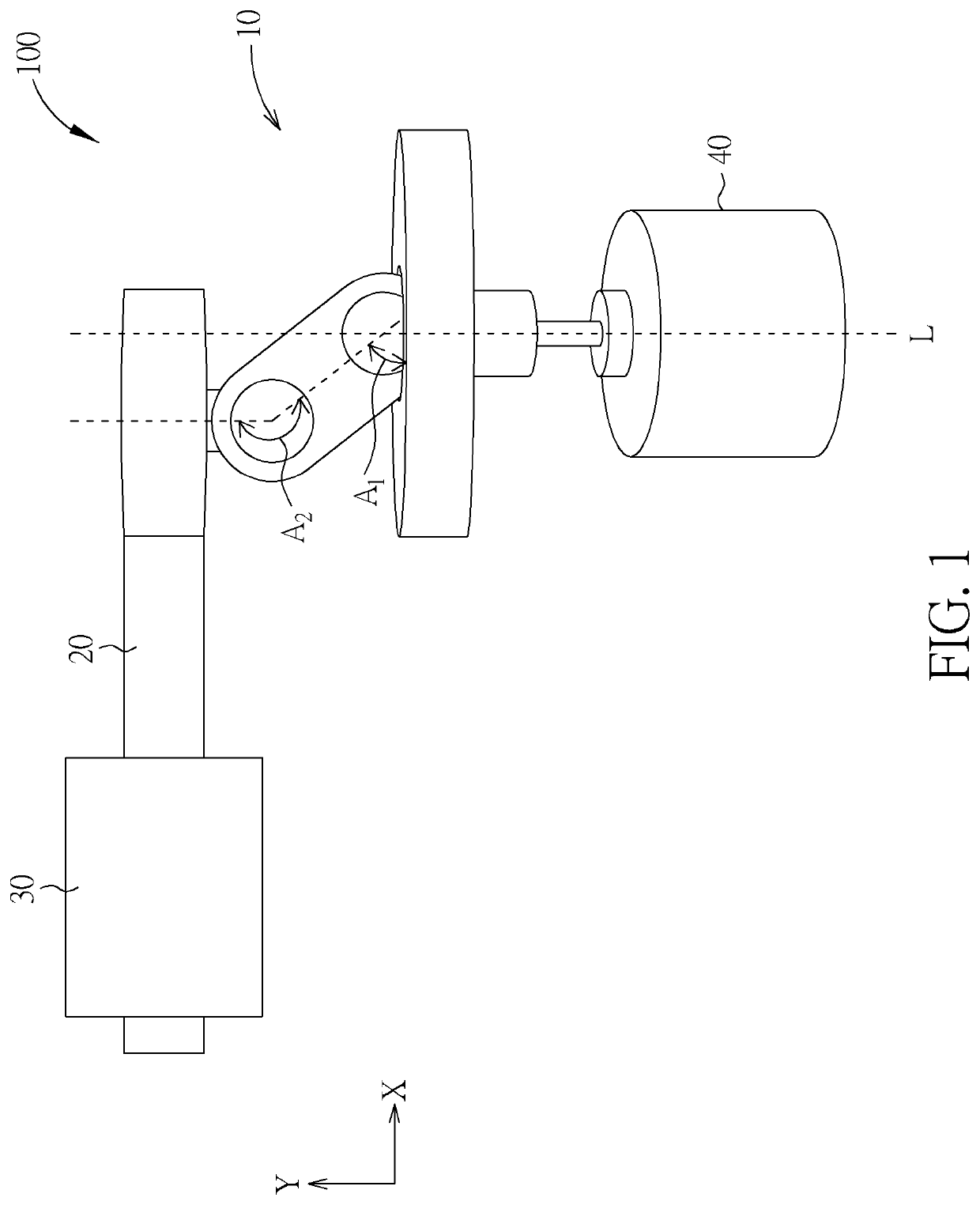
[0036]Please refer to FIG. 5. FIG. 5 is a diagram of the linear driving mechanism 100 with a stroke cycle according to the present invention. As shown in FIG. 5, a stroke S is defined by a distance between a dead center at the top and a dead center at the bottom. In an embodiment, a length of the first shaft 121 can be 20 millimeters, a diameter of the seat 11 can be 40 millimeters, the first included angle A1 can be 68 degrees, and the stroke S can be about 15 millimeters. When the linear moving component 20 moves close to or away from the seat 11 along the Y direction, i.e., a first direction, parallel to the rotating axis L, the first included angle A1 and the second included angle A2 change accordingly making the stroke S of the linear moving component 20 to change along the X direction, i.e., a second direction, substantially perpendicular to the rotating axis L. For example, when the linear moving component 20 moves away from the seat 11 along the Y direction to increase the f...

second embodiment

[0039]Please refer to FIG. 9. FIG. 9 is a diagram of the linear driving mechanism 200 with a stroke cycle according to the present invention. As shown in FIG. 9, the stroke S is defined by a distance between a dead center at the top and a dead center at the bottom. In an embodiment, a length of the first shaft 521 can be 20 millimeters, the diameter of the seat 51 can be 22 millimeters, the first included angle A1 between the first shaft 521 and the seat 51 can be 60 degrees. When the linear moving component 60 moves close to the seat 51 along the Y direction parallel to the rotating axis L, a displacement of a portion of the first shaft 521, which is located inside the driving slot 63 and applies force to the two long inner walls 621, along the X direction is increased. As a result, it causes an increase of the stroke S of the linear moving component 60 along the X direction. For example, when the linear moving component 60 is at a lowest position on the first shaft 521, the stroke...


PUM

PropertyMeasurementUnit
diameteraaaaaaaaaa
diameteraaaaaaaaaa
diameteraaaaaaaaaa

Abstract

The linear driving mechanism includes a main body, a linear moving component, a guiding component and a driving component. The main body includes a seat and a moving shaft. The driving component is connected to a rotating shaft of the seat. The moving shaft passes through a driving slot formed on the linear moving component. The guiding component is for guiding a linear movement of the linear moving component. A stroke of the linear moving component of the linear driving mechanism can be changed by approaching or distancing the linear moving component and the seat of the main body to increase or decrease the displacement of the moving shaft located inside the driving slot. Therefore, the linear driving mechanism has not only simple structure but also flexibility in use.

Description

BACKGROUND OF THE INVENTION1. Field of the Invention[0001]The present invention relates to a linear driving mechanism, and particularly, to a linear driving mechanism with variable stroke varied by a slanted moving shaft.2. Description of the Prior Art[0002]Handheld massagers can relieve muscle tension. The massagers currently available on the market are with massaging heads directly connected to propulsion mechanisms driven by motors to perform linear reciprocating movement. However, techniques of prior arts solely allow the motor to drive the massaging head to perform the linear reciprocating movement at varying speeds, that is, the speed of the linear reciprocating movement is adjustable, but the stroke of the linear reciprocating movement is fixed. Therefore, it causes the impact depth of the massaging head immutable, which limits further application of the mechanism.SUMMARY OF THE INVENTION[0003]The objective of the present invention is to provide designs of a linear driving me...

Claims


Application Information

Patent Timeline
Patent Type & Authority Applications(United States)
IPC IPC(8): F16H21/20A61H23/00
CPCA61H2201/149A61H2201/0153A61H23/006F16H21/20A61H23/0254B23D49/165
Inventor CHANG, WEI-YUCHEN, CHIH-RONG
Owner CHOK DEE TRADING CO LTD
Why Eureka
Try Eureka