
Fast binary counters based on symmetric stacking and methods for same

a counter and binary technology, applied in the field of logic circuits, to achieve the effect of saving power and speed

Active Publication Date: 2020-12-17
THE RES FOUND OF STATE UNIV OF NEW YORK
View PDF0 Cites 4 Cited by
  • Summary
  • Abstract
  • Description
  • Claims
  • Application Information

AI Technical Summary

Benefits of technology

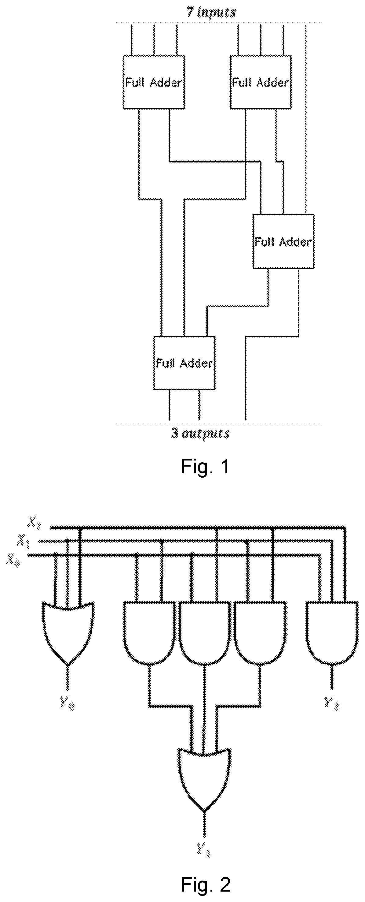
The present invention is a method for binary counting using a symmetric bit-Stacking approach. This technique allows for the efficient addition of partial products in binary multiplier circuits. The counters built using this method achieve higher speeds and save power compared to other counters due to the absence of XOR gates and multiplexers on the critical path. The use of 6:3 Counters based on the disclosed method outperforms both standard Wallace Tree multipliers and existing 7:3 Counters.

Problems solved by technology

This is due to the lack of XOR gates and multiplexers on the critical path.

Method used


Image

  • Fast binary counters based on symmetric stacking and methods for same
  • Fast binary counters based on symmetric stacking and methods for same
  • Fast binary counters based on symmetric stacking and methods for same

Examples


first embodiment

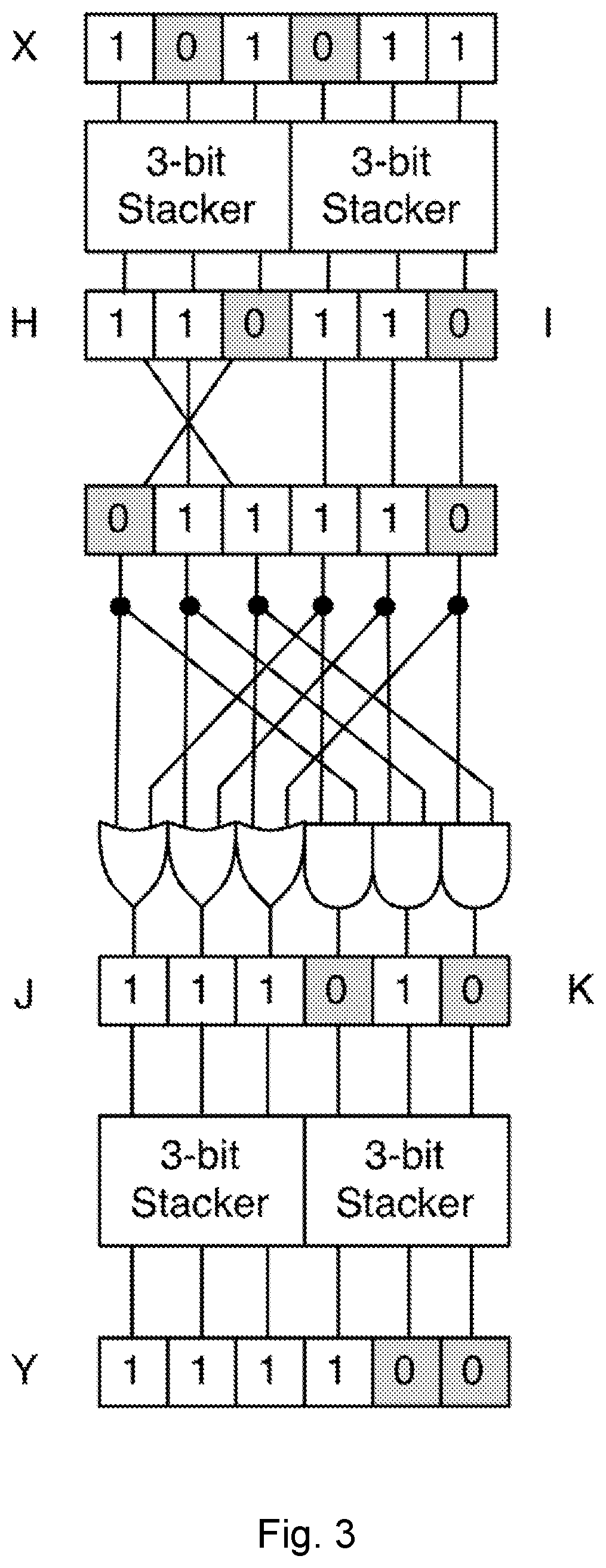
[0037]In a first embodiment, the present disclosure may be embodied as a method of stacking a 2b-bit binary vector. The 2b-bit vector is split into a first set of b bits, and a second set of b bits. No bits of the 2b-bit vector are used in both the first set and the second set. The method includes stacking the first set such that any bits having a value of ‘1’ occupy the least significant bits. The second set is stacked such that any bits having a value of ‘1’ occupy the most significant bits. In some embodiment, the first set may be stacked such that the ‘1’ bits occupy the most significant bits and then the set is reversed.

[0038]For each bit of the first set and the second set, determine if a bit of the first set or a corresponding bit of the second set has a value of ‘1’. If so, a corresponding bit of a third set is set to ‘1’. For each bit of the first set and the second set, determine if a bit of the first set and a corresponding bit of the second set has a value of ‘1’. If so,...

case 2

[0067] c≥b. This means that k+1≥b so we have b−k≤l. In this case, the regions i≥b−k and i

Pc(J)=k+l−(k+l−b)=b  (28)

Pc(K)=k+l−b=c−b  (29)

Namely, the J vector will be completely full of ‘1’s and the remaining ‘1’ bits will appear in the K vector. We can verify:

Pc(J)+Pc(K)=b+c−b=c  (30)

Therefore, the number of ‘1’ bits is unchanged.

[0068]We have therefore demonstrated that the J and K vectors contain the same number of ‘1’ bits as X, but all of the J bits will become ‘1’ before any of the K nits become ‘1’. We will pass both J and K into b-bit stackers, and let Y be the concatenated output of these two stackers.

6:3 Counter: Conversion to Binary Count

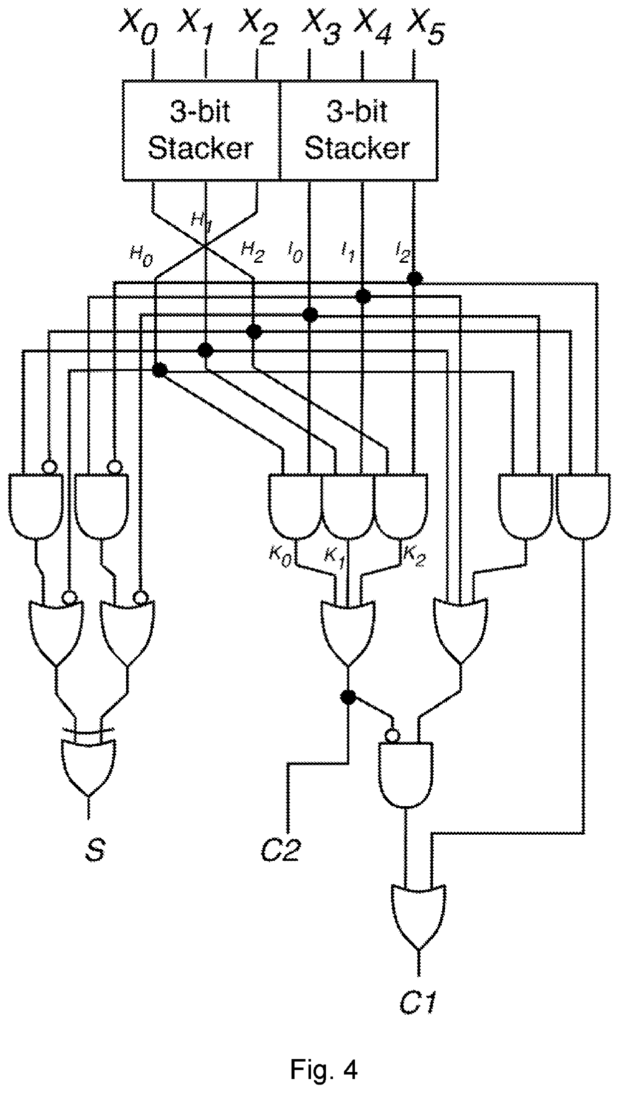
[0069]We will now use the bit stacking method defined above for b=6 specifically and for general b above to create a 6:3 counter circuit. The 6:3 counter will have six binary inputs X0, . . . , X5 and produce three outputs C2, C1, and S such that the binary number C2 C1S i...


PUM


Abstract

In this paper, binary stackers and counters are presented. In an embodiment, a counter uses 3-bit stacking circuits which group the T bits together, followed by a symmetric method to combine pairs of 3-bit stacks into 6-bit stacks. The bit stacks are then converted to binary counts, producing 6:3 and 7:3 Counter circuits with no XOR gates on the critical path. This avoidance of XOR gates results in faster designs with efficient power and area utilization. In VLSI simulations, the presently-disclosed counters were 30% faster and at consumed at least 20% less power than existing parallel counters. Additionally, using the presently-disclosed counter in existing Counter Based Wallace tree multiplier architectures reduces latency and improves efficiency in terms of power-delay product for 64-bit and 128-bit multipliers.

Description

CROSS-REFERENCE TO RELATED APPLICATIONS[0001]This application claims priority to U.S. Provisional Application No. 62 / 501,731, filed on May 4, 2017, now pending, the disclosure of which is incorporated herein by reference.FIELD OF THE DISCLOSURE[0002]The present disclosure relates to logic circuits, and in particular binary counter circuits.BACKGROUND OF THE DISCLOSURE[0003]High speed, efficient addition of multiple operands is an essential operation in any computational unit. The speed and power efficiency of multiplier circuits is of critical importance in the overall performance of microprocessors. Multiplier circuits are an essential part of an arithmetic logic unit or a digital signal processor system for performing filtering and convolution. The binary multiplication of integers or fixed point numbers results in partial products which must be added to produce the final product. The addition of these partial products dominates the latency and power consumption of the multiplier....

Claims


Application Information

Patent Timeline
IPC IPC(8): G06F7/505G06F30/327
CPCG06F30/327G06F7/505G06F2113/02G06F7/48G06F7/50G06F7/607
Inventor FRITZ, CHRISTOPHERFAM, ADLY T.
Owner THE RES FOUND OF STATE UNIV OF NEW YORK
Learn More