Supercharge Your Innovation With Domain-Expert AI Agents!

Systems and methods for precise time synchronization with optical modules

a technology of precise time synchronization and optical modules, applied in the field of optical networking systems and methods, can solve the problems of time error, advanced optical modules may introduce dynamic delays, inaccurate timing, etc., and achieve the effect of reducing delay asymmetry

Active Publication Date: 2020-12-17
CIENA
View PDF0 Cites 15 Cited by
  • Summary
  • Abstract
  • Description
  • Claims
  • Application Information

AI Technical Summary

Benefits of technology

The patent text describes a technology called PTP clock functionality that allows for precise timing in optical modules. This technology can be used in a variety of applications, such as Boundary Clocks and OTN implementations. The timing circuitry can obtain reference frequencies and times from the optical system, and can use PTP messages to transfer timestamp information. Overall, this technology allows for more accurate and reliable timing in optical systems.

Problems solved by technology

Any difference between the forward and reverse path delays, known as delay asymmetry, will result in a time error if it is not compensated for.
However, some advanced optical modules may introduce dynamic delays.
These processes can introduce delay asymmetry and uncertainty that is dynamic and unpredictable, leading to inaccurate timing.

Method used


Image

  • Systems and methods for precise time synchronization with optical modules
  • Systems and methods for precise time synchronization with optical modules
  • Systems and methods for precise time synchronization with optical modules

Examples


Embodiment Construction

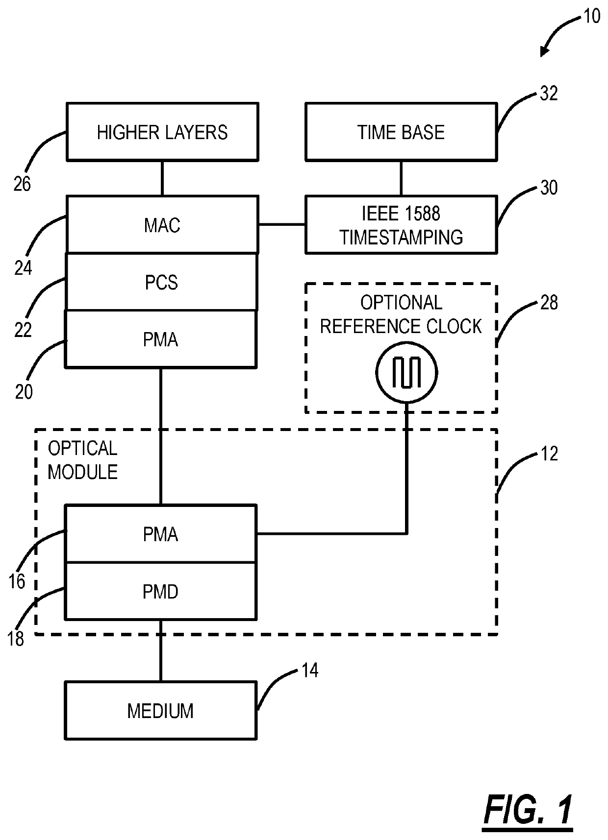
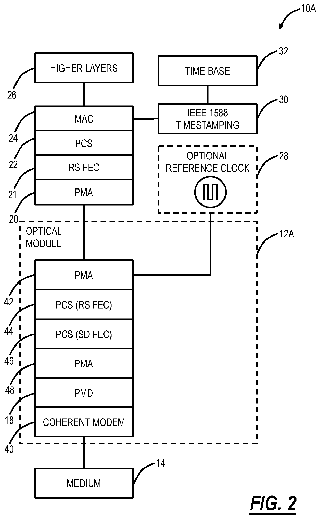
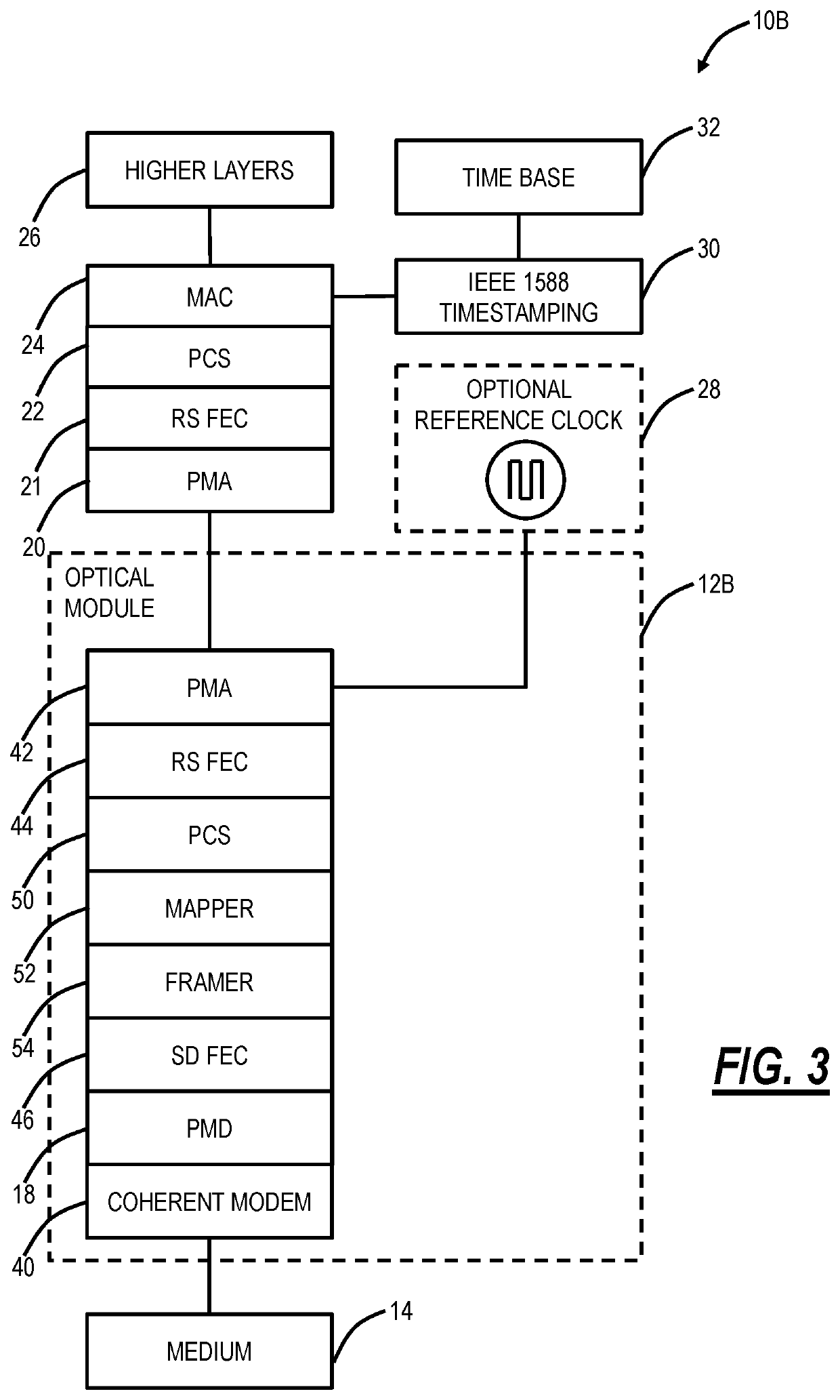
[0033]The present disclosure relates to systems and methods for precise time synchronization with optical modules. Specifically, the systems and methods include an IEEE-1588 transparent clock and / or timestamping inside a digital coherent optical module (e.g., CFP2-DCO) or onboard optics (e.g., COBO). When including timestamping inside the module, systems housing such modules can implement a transparent clock or boundary clock. The systems and methods can also implement synchronous Ethernet / OTN in the module. The systems and methods make use of the standard defined optical module electrical interface in a novel approach to enable precise timestamping and / or residence time calculation (Management Interface (MI), clock reference input, Inter-Range Instrumentation Group (TRIG)).

[0034]Variously, the systems and methods include a Transparent Clock (TC) implemented inside a coherent optical module or on-board optics, a timestamping function implemented inside a coherent optical module or o...


PUM


Abstract

An optical module for use in an optical system is disclosed, the optical module implementing Precision Time Protocol (PTP) clock functionality therein. The optical module includes an electrical interface with the optical system; circuitry connected to the electrical interface and configured to implement a plurality of functions of functionality; an optical interface connected to the circuitry; and timing circuitry connected to the electrical interface and one or more of the plurality of functions, wherein the timing circuitry is configured to implement the PTP clock functionality.

Description

FIELD OF THE DISCLOSURE[0001]The present disclosure generally relates to optical networking systems and methods. More particularly, the present disclosure relates to systems and methods for precise time synchronization with optical modules, such as pluggable modules.BACKGROUND OF THE DISCLOSURE[0002]Timing synchronization between nodes in a network is described in various standards such as IEEE 1588-2008 “Standard for a Precision Clock Synchronization Protocol for Networked Measurement and Control Systems,” ITU-T G.8265.1 / Y.1365.1 “Precision time protocol telecom profile for frequency synchronization,” ITU-T G. 8275.1 / Y1369.1 “Precision time protocol telecom profile for phase / time synchronization with full timing support from the network,” the contents of each is incorporated by reference herein. The requisite information for the transfer of precise time is (1) a time reference point, or “significant instant” to which timing information can be related, (2) the timing information its...

Claims


Application Information

Patent Timeline
Patent Type & Authority Applications(United States)
IPC IPC(8): H04L7/00H04J3/06H04B10/40
CPCH04J3/0697H04L7/0075H04J3/0667H04J3/0638H04B10/40H04Q2011/0045H04Q11/0005H04B10/516
Inventor PERRAS, DANIEL CLAUDEGAREAU, SEBASTIEN
Owner CIENA
Features
  • R&D
  • Intellectual Property
  • Life Sciences
  • Materials
  • Tech Scout
  • Unparalleled Data Quality
  • Higher Quality Content
  • 60% Fewer Hallucinations
Learn More