Robot control apparatus and robot control system

a robot control and robot technology, applied in the field of robot control apparatus, can solve the problems of reducing the accuracy of the tracking operation, unable to continue seam tracking operations, and the operation line may exit the field, so as to achieve more precise seam tracking operations

a robot control and robot technology, applied in the field of robot control apparatus, can solve the problems of reducing the accuracy of the tracking operation, unable to continue seam tracking operations, and the operation line may exit the field, so as to achieve more precise seam tracking operations

US20200398425A1Active Publication Date: 2020-12-24DAIHEN CORP

Image

  • Robot control apparatus and robot control system
  • Robot control apparatus and robot control system
  • Robot control apparatus and robot control system

Examples


Embodiment Construction

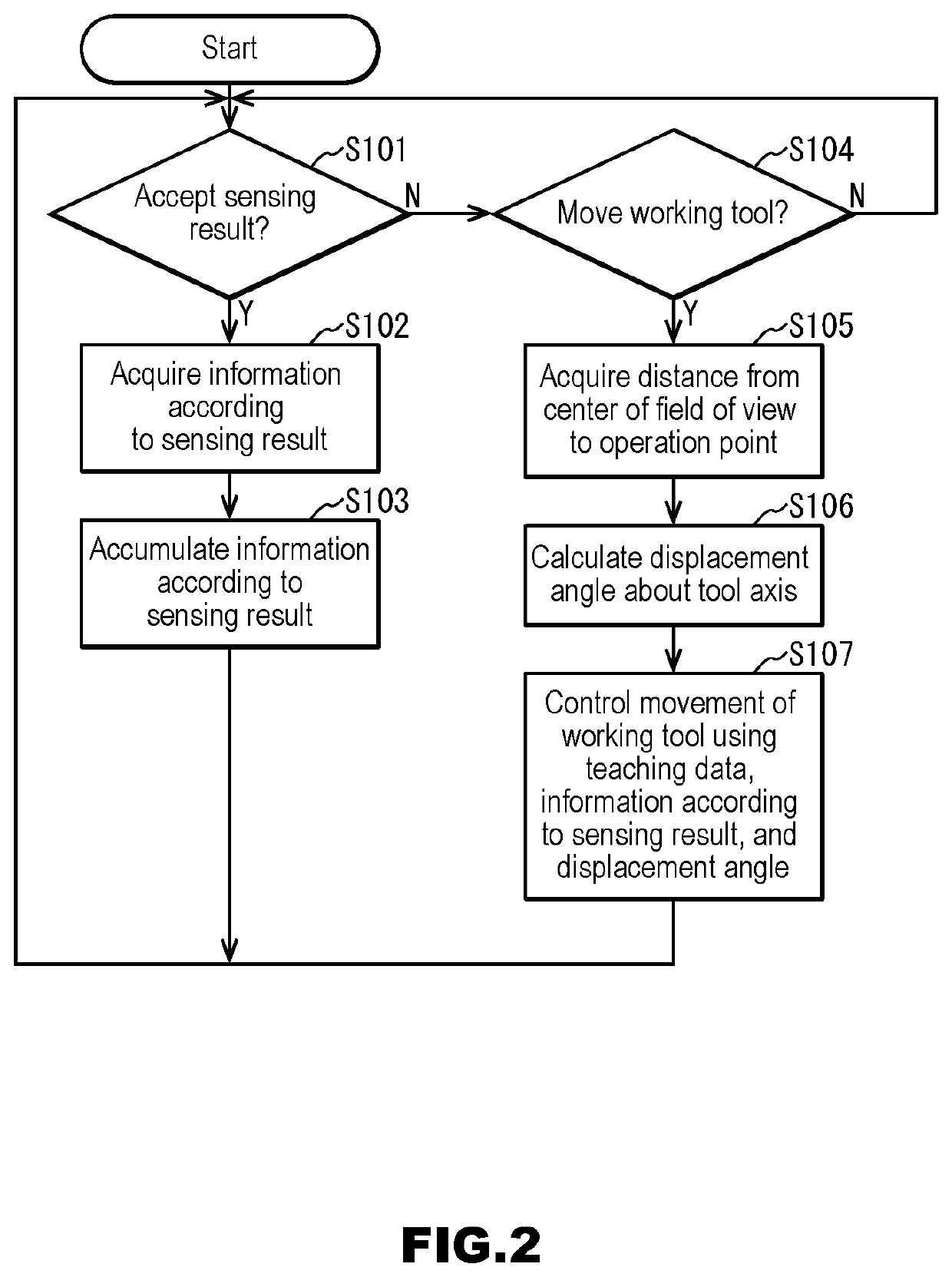
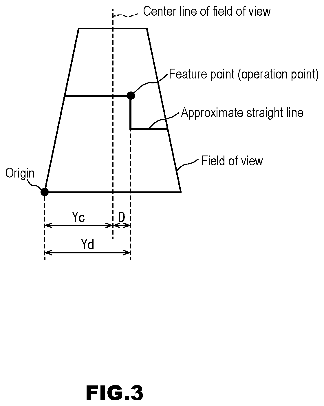
[0023]Hereinafter, a robot control system and a robot control apparatus according to the present invention will be described based on an embodiment. Note that constituent elements or steps denoted by the same reference numerals are the same as or similar to each other in the following embodiments, and thus a description thereof may not be repeated. The robot control apparatus according to this embodiment adjusts an angle about a tool axis such that an operation line is at the center of the field of view of a laser sensor in a seam tracking operation.

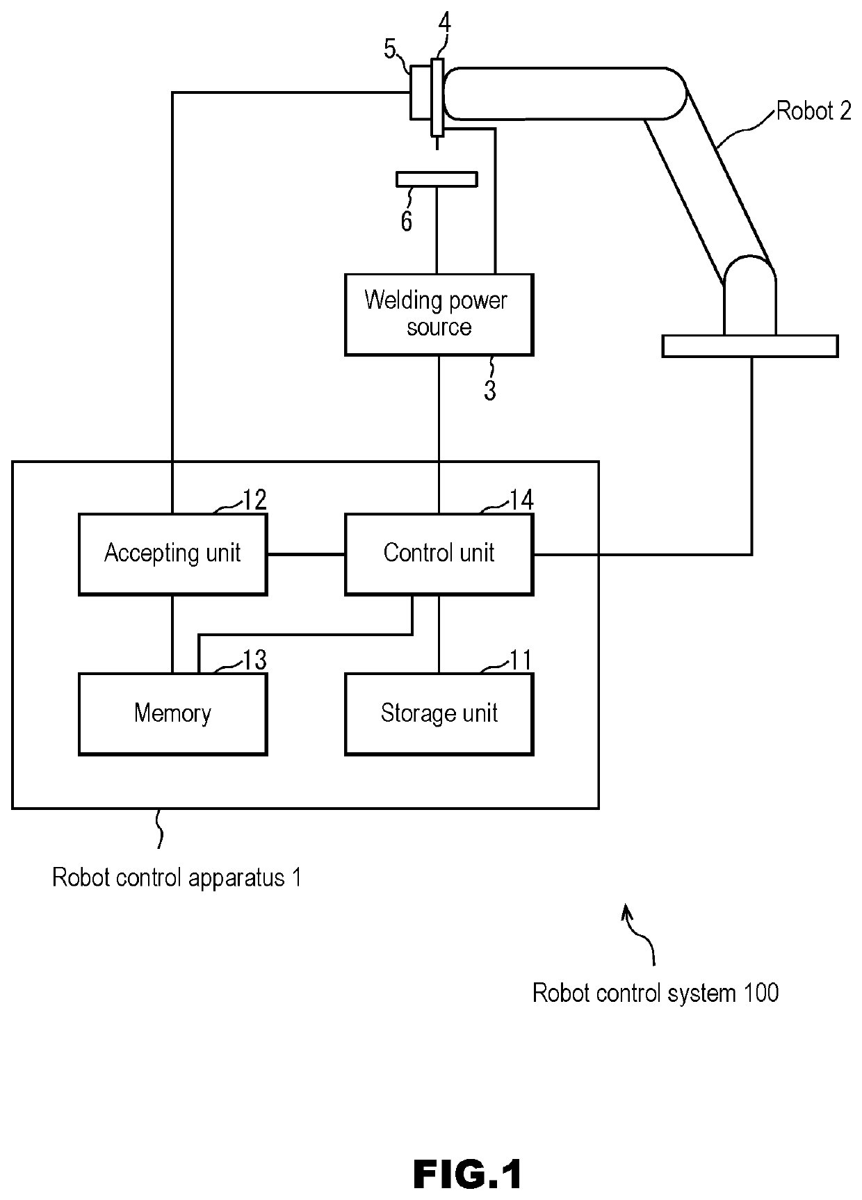
[0024]FIG. 1 is a block diagram showing the configuration of a robot control system 100 according to this embodiment. The robot control system 100 according to this embodiment includes a robot control apparatus 1, a robot 2, and a welding power source 3.

[0025]The robot control apparatus 1 controls the robot 2 and the welding power source 3. The robot 2 has a manipulator having multiple arms coupled to each other via joints that are drive...


PUM

PropertyMeasurementUnit
angleaaaaaaaaaa
heat strainaaaaaaaaaa
displacementaaaaaaaaaa

Abstract

A robot control apparatus for a more precise seam tracking operation, includes: a storage unit in which teaching data is stored; an accepting unit that accepts a sensing result of a laser sensor, from a robot including a working tool and the laser sensor attached to the working tool and configured to detect a shape of a working target before an operation of the working tool; and a control unit that moves the working tool based on the teaching data, corrects the movement of the working tool based on the sensing result, and adjusts an angle about a tool axis such that an operation point indicated by the sensing result is at a center of a field of view of the laser sensor. Accordingly, an operation line can be detected near the center of the field of view of the laser sensor, and thus more precise detection is possible.

Description

CROSS REFERENCE TO RELATED APPLICATION[0001]This application claims priority of Japanese Patent Application No. 2019-112798 filed Jun. 18, 2019. The entire contents of which are hereby incorporated by reference.FIELD OF THE INVENTION[0002]The present invention relates to a robot control apparatus and the like for moving a working tool based on a sensing result of a laser sensor.BACKGROUND OF THE INVENTION[0003]When performing welding using robots, target positions may be displaced due to heat strain of workpieces, which results in welding defects. This displacement is solved by detecting a joint position with a laser sensor and adjusting a target position of a robot (welding seam tracking) (see JP 117-129217A, for example).SUMMARY OF THE INVENTION[0004]However, since the field of view of a laser sensor is limited, if the operation line is curved with a large curvature, the operation line may exit the field of view and it may no longer be possible for the seam tracking operation to c...

Claims


Application Information

Patent Timeline
24 Dec 2020
Publication
US20200398425A1
IPC
B25J9/16
CPC
B25J9/1697; B25J9/1684; B25J9/163; B25J9/1602; B23K37/0258; B23K9/1274; B23K9/0953; B23K9/0956
Inventors
FUJISAWA, SHO