Rotating electrical machine and production method thereof

a technology of rotating electrical machines and rotating parts, which is applied in the direction of rotating parts of magnetic circuits, magnetic circuits, windings, etc., can solve the problems of damage or breakage of magnetic steel plates, broken or undeformed core plates, breakage or bending of core plates, etc., and achieve the effect of increasing the degree of elastic deformation of waves

Active Publication Date: 2020-12-24
DENSO CORP
View PDF0 Cites 5 Cited by
  • Summary
  • Abstract
  • Description
  • Claims
  • Application Information

AI Technical Summary

Benefits of technology

[0017]The above structure achieves an increased degree of elastic deformation of the wave of the end plate to ensure a required ability of the wave functioning as cushions.

Problems solved by technology

Tightly compressing the stack of the magnetic steel plate using the rivets or bolts, therefore, leads to a risk that stress may concentrate on contacts between the rivets or bolts and the magnetic steel plates, so that the magnetic steel plate is damaged or broken.
In a case where the rotating electrical machine is used in a vehicle, mechanical impact or vibration may be exerted on the rotating electrical machine, thereby leading to a risk that stress may temporarily concentrate on the contacts between the rivets or bolts and the magnetic steel plates, resulting in them being broken or undesirably deformed.
The concentration of stress on the core plates, therefore, it may result in breakage or bending of the core plates.
If the through-holes are formed in the plate strip, after which the plate strip is machined into a circular ring shape, it will cause the through-holes to absorb distortion arising from the machining of the plate strip, thereby resulting in a decrease in amount by which the wave of the end plate is elastically deformed.

Method used


Image

  • Rotating electrical machine and production method thereof
  • Rotating electrical machine and production method thereof
  • Rotating electrical machine and production method thereof

Examples


first embodiment

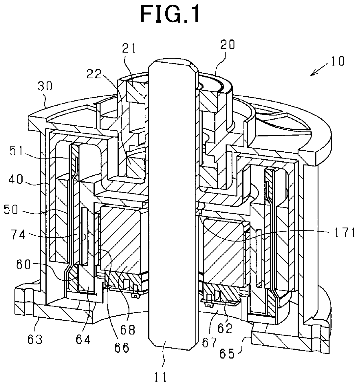
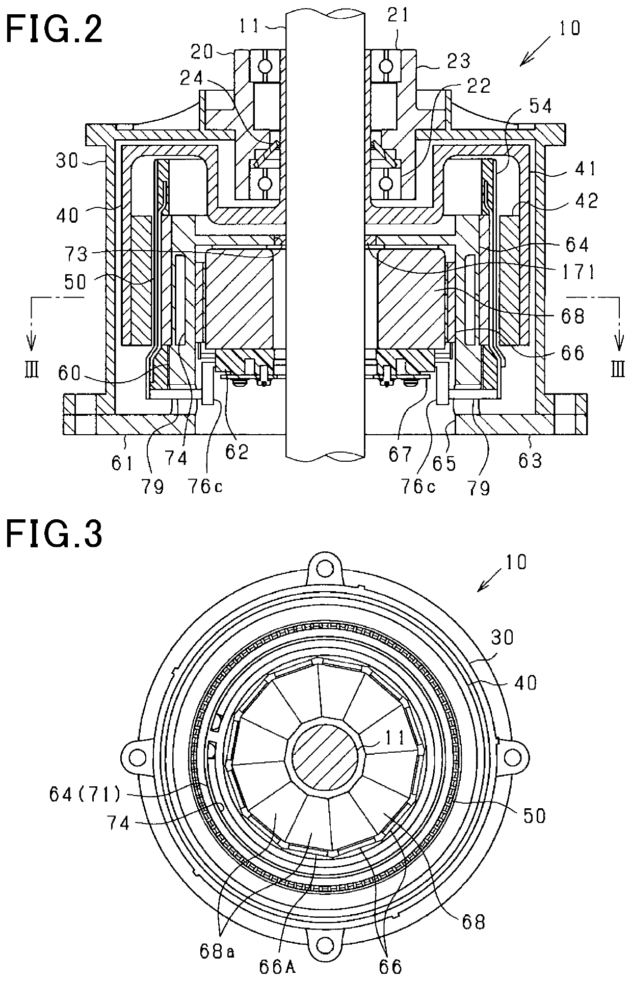
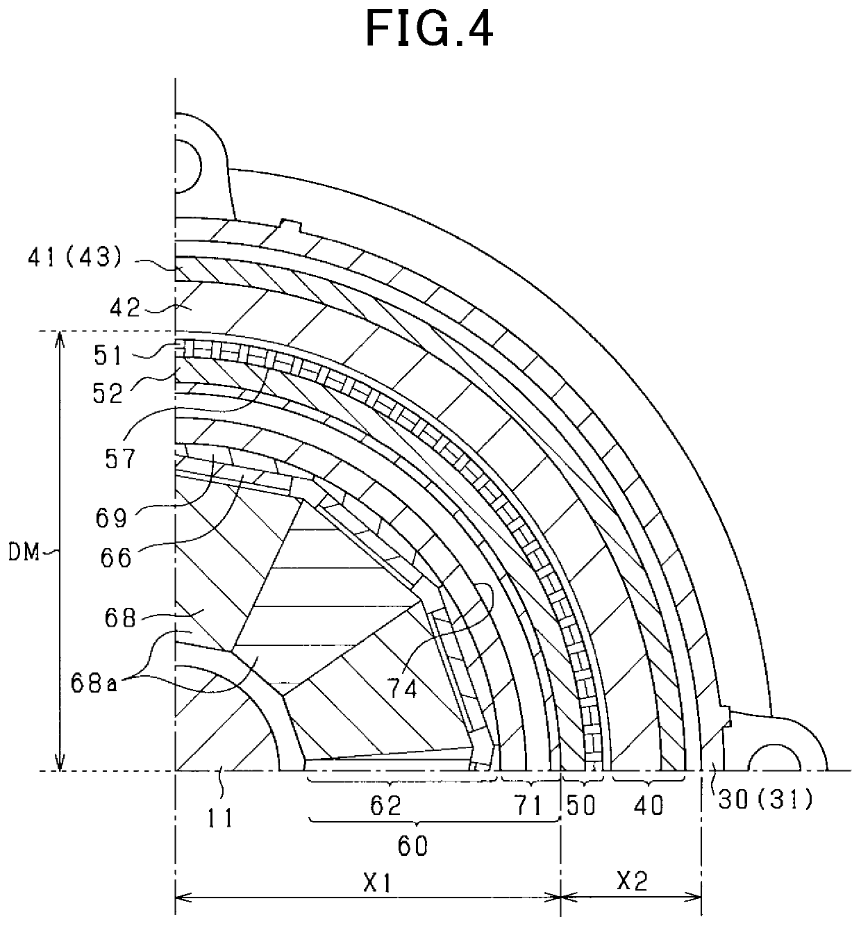
[0107]The rotating electrical machine 10 in this embodiment is a synchronous polyphase ac motor having an outer rotor structure (i.e., an outer rotating structure). The outline of the rotating electrical machine 10 is illustrated in FIGS. 1 to 5. FIG. 1 is a perspective longitudinal sectional view of the rotating electrical machine 10. FIG. 2 is a longitudinal sectional view along the rotating shaft 11 of the rotating electrical machine 10. FIG. 3 is a transverse sectional view (i.e., sectional view taken along the line III-III in FIG. 2) of the rotating electrical machine 10 perpendicular to the rotating shaft 11. FIG. 4 is a partially enlarged sectional view of FIG. 3. FIG. 5 is an exploded view of the rotating electrical machine 10. FIG. 3 omits hatching showing a section except the rotating shaft 11 for the sake of simplicity of the drawings. In the following discussion, a lengthwise direction of the rotating shaft 11 will also be referred to as an axial direction. A radial dire...

second embodiment

[0278]In this embodiment, the polar anisotropic structure of the magnet unit 42 of the rotor 40 is changed and will be described below in detail.

[0279]The magnet unit 42 is, as clearly illustrated in FIGS. 22 and 23, made using a magnet array referred to as a Halbach array. Specifically, the magnet unit 42 is equipped with the first magnets 131 and the second magnets 132. The first magnets 131 have a magnetization direction (i.e., an orientation of a magnetization vector thereof) oriented in the radial direction of the magnet unit 42. The second magnets 132 have a magnetization direction (i.e., an orientation of the magnetization vector thereof) oriented in the circumferential direction of the magnet unit 42. The first magnets 131 are arrayed at a given interval away from each other in the circumferential direction. Each of the second magnets 132 is disposed between the first magnets 131 arranged adjacent each other in the circumferential direction. The first magnets 131 and the sec...

first modification

[0293]In the above embodiment, the outer peripheral surface of the stator core 52 has a curved surface without any irregularities. The plurality of conductor groups 81 are arranged at a given interval away from each other on the outer peripheral surface of the stator core 52. This layout may be changed. For instance, the stator core 52 illustrated in FIG. 25 is equipped with the circular ring-shaped yoke 141 and the protrusions 142. The yoke 141 is located on the opposite side (i.e., a lower side, as viewed in the drawing) of the stator winding 51 to the rotor 40 in the radial direction. Each of the protrusions 142 protrudes into a gap between a respective two of the straight sections 83 arranged adjacent each other in the circumferential direction. The protrusions 142 are arranged at a given interval away from each other in the circumferential direction radially outside the yoke 141, i.e., close to the rotor 40. Each of the conductor groups 81 of the stator winding 51 engages the p...


PUM


Abstract

A rotating electrical machine is equipped with a rotor and a stator. The rotor includes a magnet unit and a rotor core retaining the magnet unit. The rotor core is made of a stack of annular core plates and an annular end plate mounted on an end of the stack of the core plates. The end plate has a deformable wave shape. The stack of the core plates and the end plate has formed therein through-holes extending through a length thereof. Bar-shaped fastening members, such as rivets, which have flanges on ends thereof are inserted into the through-holes with the flanges pressing the end plate to elastically deform the wave shape of the end plate, thereby tightly gripping the stack of the core plates in the lengthwise direction. This minimizes concentration of stress on the core plates to eliminate a risk of damage or breakage of the rotor.

Description

CROSS REFERENCE TO RELATED DOCUMENT[0001]The present application claims the benefit of priority of Japanese Patent Application No. 2019-114903 filed on Jun. 20, 2019, the disclosure of which is incorporated herein by reference.BACKGROUND1 Technical Field[0002]This disclosure relates generally to a rotating electrical machine and a production method thereof.2 Background Art[0003]IPM (Interior Permanent Magnet) rotors which have a rotor core made of a stack of magnetic steel plates and magnets disposed in magnet chambers formed in the stator core are becoming widely used as rotating electrical machines. Magnets used in such a rotor may be implemented by those taught in Japanese Patent Publication No. 2014-93859. The magnets in this publication are each designed to create a surface magnetic flux density approximating a sine wave which changes more gradually than radial magnets, thereby resulting in a decrease in eddy current loss and also enabling the magnetic flux density to be increa...

Claims


Application Information

Patent Timeline
Patent Type & Authority Applications(United States)
IPC IPC(8): H02K1/27H02K1/28H02K21/14H02K29/03H02K3/04
CPCH02K3/04H02K29/03H02K21/14H02K1/28H02K2213/03H02K1/276H02K5/20H02K21/22H02K5/1735H02K3/47H02K3/28H02K7/14H02K5/225H02K11/33H02K3/522H02K2203/09H02K11/215
Inventor TAKAHASHI, YUKI
Owner DENSO CORP
Why Eureka
Try Eureka