Exhaust gas aftertreatment device

Active Publication Date: 2020-12-31
VITESCO TECH GMBH
View PDF0 Cites 0 Cited by
  • Summary
  • Abstract
  • Description
  • Claims
  • Application Information

AI Technical Summary

Benefits of technology

The present invention aims to provide a device for exhaust gas aftertreatment that can clean exhaust gas to meet legal requirements and reduce noise emissions while minimizing pressure loss in the exhaust line.

Problems solved by technology

The disadvantage with this structure of the exhaust line is that the catalytic converters generally have a significantly larger diameter than the pipes used for connection.
Consequently, there are a number of abrupt changes of flow cross section during flow through the exhaust system from the internal combustion engine to the exhaust outlet.
These changes in the flow cross section, especially the transitions from the sections of relatively large flow cross section to sections of relatively small flow cross section, lead to severe pressure losses, which is disadvantageous for maximum efficiency of operation of the internal combustion engine.

Method used


Image

  • Exhaust gas aftertreatment device
  • Exhaust gas aftertreatment device

Examples


Embodiment Construction

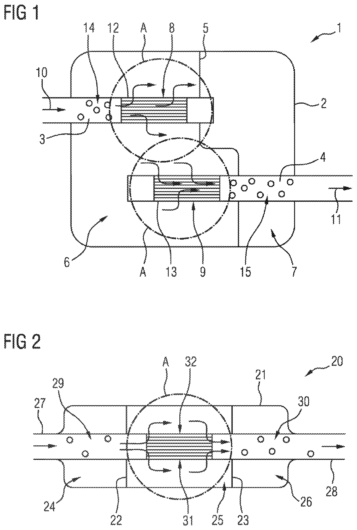
[0031]FIG. 1 shows a muffler 1 formed by a housing 2. An exhaust gas flow can flow into the housing 2 along an inflow section 3 and can flow out of the housing 2 through an outflow section 4. The inflow section 3 and the outflow section 4 are formed by pipes, which are preferably connected to the remainder of the exhaust line.

[0032]The volume of the muffler 1 is divided in the interior into two partial volumes 6 and 7 by a partition wall 5. Two catalytic converters 8 and 9 are arranged in the first partial volume 6. The catalytic converters are designed as metal honeycomb bodies and have a plurality of flow channels, through which flow can take place substantially axially in the inflow direction 10 and the outflow direction 11. The metal honeycomb bodies are arranged in a casing tube 12 and 13, respectively, and are connected to the latter in a materially bonded manner. The first catalytic converter 8 is connected directly to the inflow section 3, and the second catalytic converter ...


PUM

PropertyMeasurementUnit
Sizeaaaaaaaaaa
Volumeaaaaaaaaaa

Abstract

A device for the aftertreatment of exhaust gases of an internal combustion engine, having at least one catalytic converter, through which exhaust gas can flow, and at least one muffler formed by a closed volume and through which exhaust gas can flow along an inflow section to an outflow section. The catalytic converter is formed by a honeycomb body that has a plurality of flow channels through which exhaust gas can flow. The honeycomb body is accommodated in a casing tube, which surrounds the honeycomb body, and is connected to the casing tube in a materially bonded manner. The catalytic converter is arranged in the interior of the muffler.

Description

CROSS REFERENCE TO RELATED APPLICATIONS[0001]This is a U.S. national stage of Application No. PCT / EP2019 / 054759 filed Feb. 26, 2019. Priority is claimed on German Application No. DE 10 2018 203 066.9 filed Mar. 1, 2018 the content of which is incorporated herein by reference.BACKGROUND OF THE INVENTION1. Field of the Invention[0002]The invention relates to a device for aftertreatment of exhaust gases of an internal combustion engine, having at least one catalytic converter, through which exhaust gas can flow, and at least one muffler formed by a closed volume and through which exhaust gas can flow along an inflow section to an outflow section, wherein the catalytic converter is formed by a honeycomb body that has a plurality of flow channels through which exhaust gas can flow, wherein the honeycomb body is accommodated in a casing tube, which surrounds the honeycomb body, and is connected to the casing tube in a materially bonded manner.2. Description of Related Art[0003]The catalyt...

Claims


Application Information

Patent Timeline
IPC IPC(8): F01N3/28F01N1/02B01J35/04
CPCF01N2490/02F01N2330/32F01N3/2803B01J35/04F01N2490/15F01N1/02F01N2230/04F01N3/2885F01N1/089F01N3/281F01N3/2821F01N13/017F01N2470/02F01N2470/04F01N2490/04F01N2490/20F01N2530/04B01J35/56
Inventor HIRTH, PETERKONIECZNY, KATRINNAGEL, THOMASSTOCK, HOLGER
Owner VITESCO TECH GMBH
Why Eureka
Try Eureka