
Optimal sensor selection and fusion for heat exchanger fouling diagnosis in aerospace systems

a technology of aerospace systems and sensors, applied in the direction of instruments, energy-efficient board measures, lighting and heating apparatus, etc., can solve the problems of aircraft heat exchanger performance degradation, difficult diagnosis of fouling, and high cos

Active Publication Date: 2020-12-31
UNIV OF CONNECTICUT
View PDF0 Cites 0 Cited by
  • Summary
  • Abstract
  • Description
  • Claims
  • Application Information

AI Technical Summary

Benefits of technology

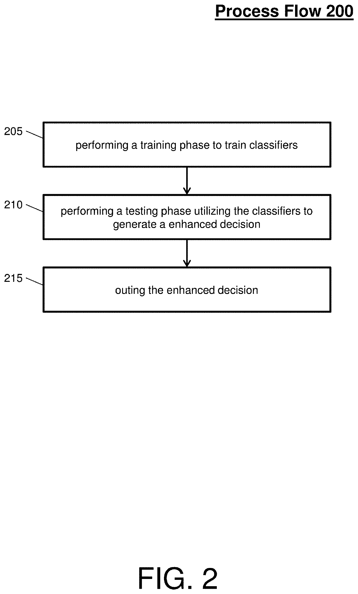
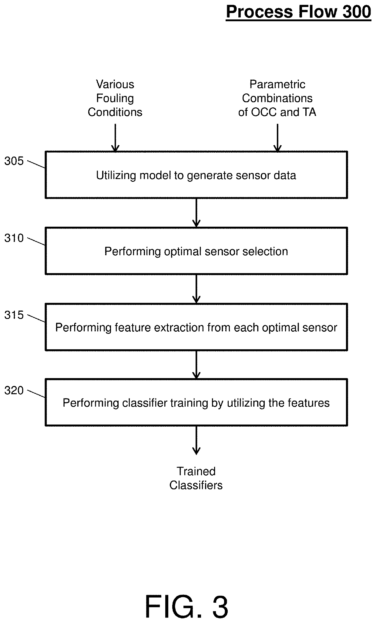
The invention is related to techniques for detecting fouling on heat exchangers in complex networked systems, such as air management systems. The patent describes a method that involves training classifiers that can identify different fouling conditions associated with the heat exchanger and then using these classifiers to test sensor data from optimal sensors to determine if the fouling is actually occurring on the heat exchanger. This invention can help to improve the efficiency and reliability of heat exchangers in complex systems.

Problems solved by technology

Typically, aircraft heat exchangers suffer from performance degradation due to a phenomenon called fouling.
Fouling occurs when unwanted accumulation of external substances, debris, and / or organisms contaminate a surface of heat exchanger fins.
Further, complex environments, such as aerospace systems, operate under varying altitudes levels, ambient temperatures, passenger loads, and other uncertainties that make fouling diagnosis very challenging.
Moreover, determining the critical sensors to analyze for fouling diagnosis is difficult due to the interconnections and interdependencies between different components and sensors.
These methodologies are also prone to high false alarm rate and missed detections.
Furthermore, since the air management system has a large sensor suite, large amount of data are generated that make the analysis computationally complex.
Further, the current methodologies do not perform multi-nary classification of fouling severities, do not present the correct classification rate (CCR) and the false alarm rate, do not address the problem of optimal sensor selection and fusion for fouling diagnosis, and are also very susceptible to noise in the data.

Method used


Image

  • Optimal sensor selection and fusion for heat exchanger fouling diagnosis in aerospace systems
  • Optimal sensor selection and fusion for heat exchanger fouling diagnosis in aerospace systems
  • Optimal sensor selection and fusion for heat exchanger fouling diagnosis in aerospace systems

Examples


Embodiment Construction

[0013]A detailed description of one or more embodiments of the disclosed apparatus and method are presented herein by way of exemplification and not limitation with reference to the Figures.

[0014]As indicated above, the current methodologies for detecting fouling provide limited efficiency and accuracy due to the large amount of data and limited analysis capabilities. Thus, what is needed is a mechanism that utilizes algorithms of optimal sensor selection and fouling diagnosis in conjunction with machine learning tools.

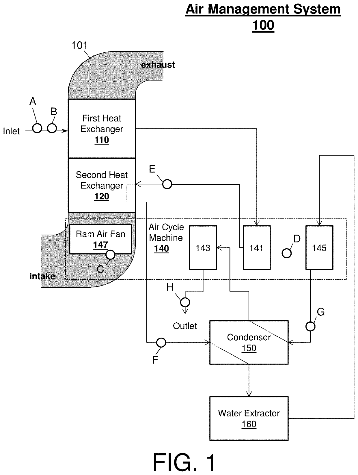
[0015]In general, embodiments disclosed herein may include a system, method, and / or computer program product (herein diagnosis system) that performs a heat exchanger fouling diagnosis of a complex networked system. Fouling diagnosis is a detection and identification of a fouling level of a blocked or congested heat exchanger, which is unable to cool a medium at an optimal efficiency, within the complex networked system.

[0016]The complex networked system (e.g., an envi...


PUM

PropertyMeasurementUnit
temperatureaaaaaaaaaa
fouling severityaaaaaaaaaa
temperaturesaaaaaaaaaa

Abstract

A system and method that determines whether a heat exchanger within a complex networked system is fouling is provided. The system and method includes training classifiers indicative of a plurality of fouling conditions associated with the heat exchanger and testing the classifiers with optimal sensor data from optimal sensors to determine whether the fouling is being experienced by the heat exchanger.

Description

CROSS-REFERENCE TO RELATED APPLICATIONS[0001]This application is a division of U.S. application Ser. No. 14 / 700,769 filed Apr. 30, 2015, the disclosure of which is incorporated herein by reference in its entirety.BACKGROUND OF THE INVENTION[0002]In general, a component of the air management system of an aircraft is a heat exchanger, which ensures proper cooling of the engine bleed air. Typically, aircraft heat exchangers suffer from performance degradation due to a phenomenon called fouling. Fouling occurs when unwanted accumulation of external substances, debris, and / or organisms contaminate a surface of heat exchanger fins. Further, complex environments, such as aerospace systems, operate under varying altitudes levels, ambient temperatures, passenger loads, and other uncertainties that make fouling diagnosis very challenging. Moreover, determining the critical sensors to analyze for fouling diagnosis is difficult due to the interconnections and interdependencies between different...

Claims


Application Information

Patent Timeline
Patent Type & Authority Applications(United States)
IPC IPC(8): G01N17/00F28F27/00B64D13/06
CPCF28F27/00G01N17/008B64D2013/0618B64D13/06Y02T50/50
Inventor NAJJAR, NAYEFF A.GUPTA, SHALABHHARE, JAMES Z.LEAPER, GREGORY R.D'ORLANDO, PAUL M.WALTHALL, RHONDAPATTIPATI, KRISHNA
Owner UNIV OF CONNECTICUT
Learn More