Current Collector Arrangement for a Vehicle
- Summary
- Abstract
- Description
- Claims
- Application Information
AI Technical Summary
Benefits of technology
Problems solved by technology
Method used
Image
Examples
Embodiment Construction
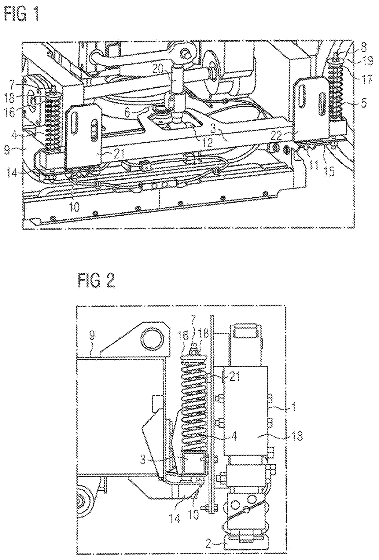
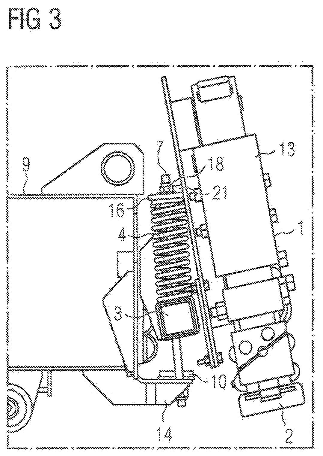
[0030]A carrier 3, represented in FIG. 1 as an oblique projection, of an exemplary embodiment of an inventive current collector arrangement, is connected via a joint 6, which is formed as a center pin, to a bogie frame 9 of a bogie of a rail vehicle and rests on a first elastic element 10 and a second elastic element 11, which are formed as buffers. The first elastic element 10 is connected to a first bracket 14, and the second elastic element 11 is connected to a second bracket 15. The first bracket 14 and the second bracket 15 are welded to the bogie frame 9.
[0031]In accordance with the invention, it is also conceivable to couple the carrier 3 to a body of the rail vehicle, where in this case the joint 6, the first bracket 14 and the second bracket 15 are connected to the body.
[0032]A first rod 7 is pivotably mounted on the first bracket 14 about an axis that extends parallel to a longitudinal axis of the bogie or parallel to the direction of travel of the bogie.
[0033]A second rod...
PUM
 Abstract
Description
Claims
Application Information
 - R&D
- Intellectual Property
- Life Sciences
- Materials
- Tech Scout
- Unparalleled Data Quality
- Higher Quality Content
- 60% Fewer Hallucinations
Browse by: Latest US Patents, China's latest patents, Technical Efficacy Thesaurus, Application Domain, Technology Topic, Popular Technical Reports.
© 2025 PatSnap. All rights reserved.Legal|Privacy policy|Modern Slavery Act Transparency Statement|Sitemap|About US| Contact US: help@patsnap.com


