Rubber-coated cord manufacturing device and rubber-coated cord manufacturing method

a technology of manufacturing device and rubber coating, which is applied in the direction of coating, other domestic articles, fibre treatment, etc., can solve the problem of damage to the extrusion head b>2/b>, and achieve the effect of preventing the occurrence of spewing rubber, reducing scrap, and reducing the burden on the operator

Inactive Publication Date: 2021-01-14
SUMITOMO RUBBER IND LTD
View PDF0 Cites 2 Cited by
  • Summary
  • Abstract
  • Description
  • Claims
  • Application Information

AI Technical Summary

Benefits of technology

[0044]According to the present invention, can be provided a rubber-coated cord manufacturing technique, wherein occurrence of spew rubber is prevented during the rubber-coate

Problems solved by technology

However, if the head pressure is abnormally high, th

Method used


Image

  • Rubber-coated cord manufacturing device and rubber-coated cord manufacturing method
  • Rubber-coated cord manufacturing device and rubber-coated cord manufacturing method
  • Rubber-coated cord manufacturing device and rubber-coated cord manufacturing method

Examples


example

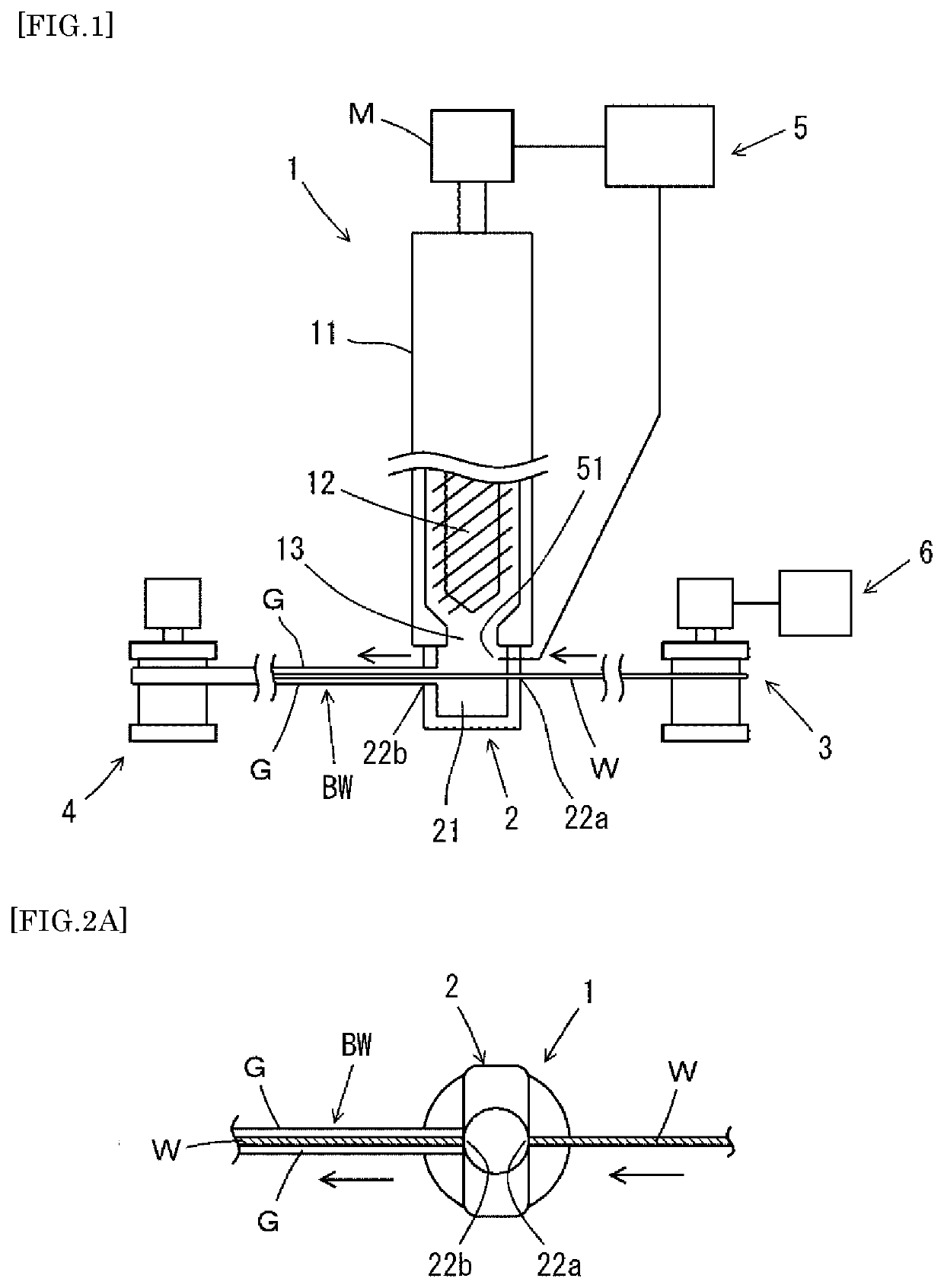
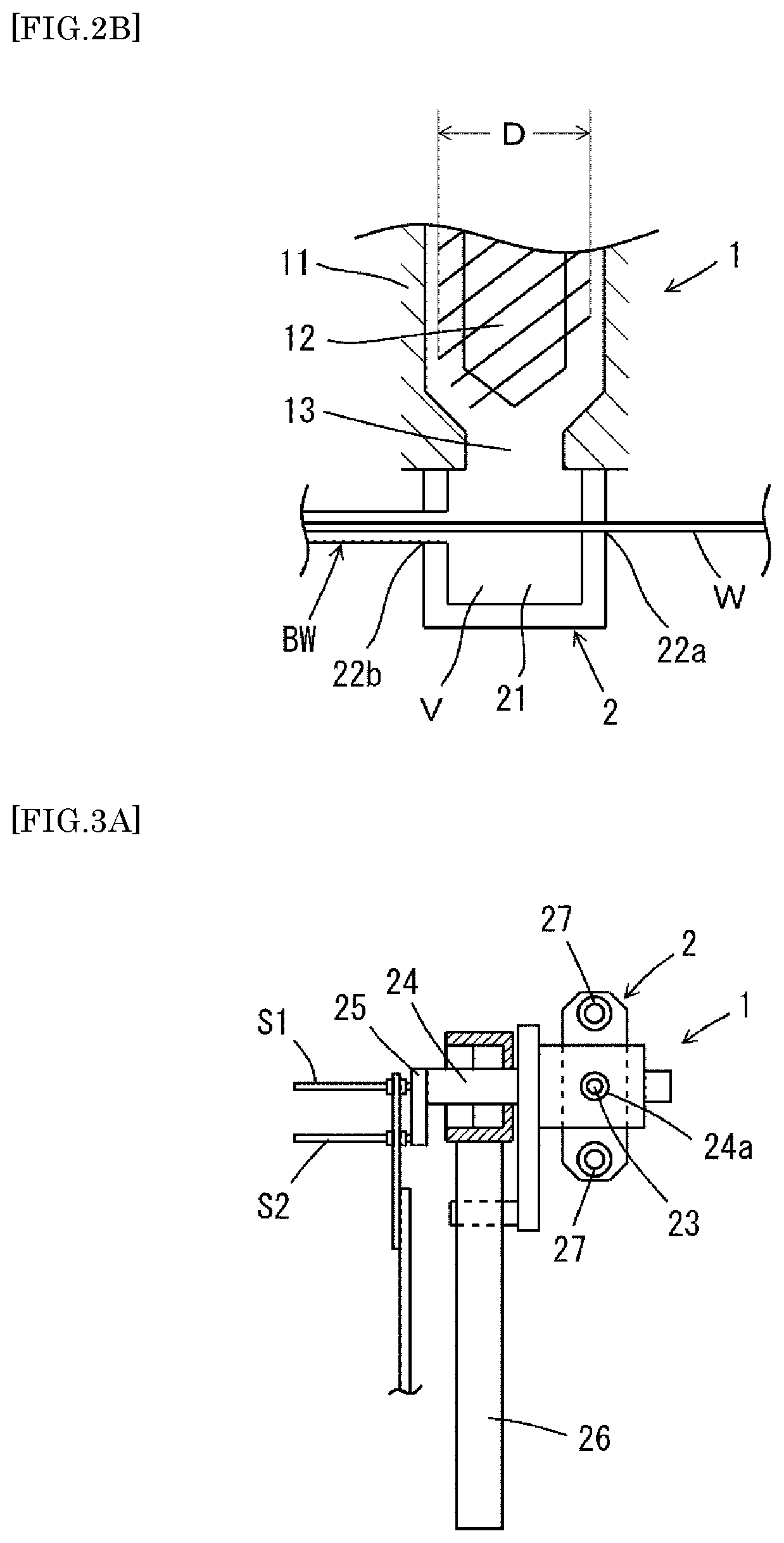
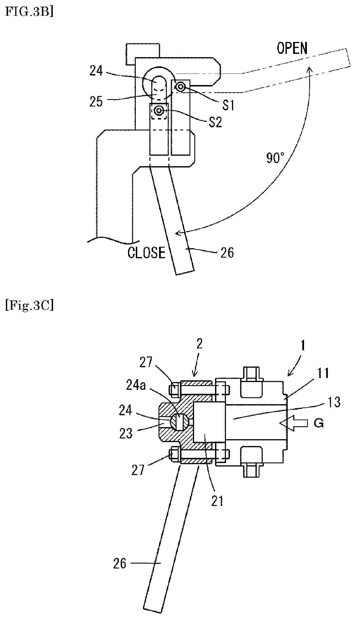
[0089]Hereinafter, the present invention will be explained more specifically based on examples. In the examples, the experiments are conducted by using a bead manufacturing device which is an example of a rubber-coated cord manufacturing device.

experiment 1

1. Experiment 1

(1) Production of the Bead

[0090]In Experiment 1, a bead was produced with a process of the present invention by changing the head pressure at 11 levels in the range of 5-15 MPa, and the effects of equipment on the bead manufacturing device were evaluated. In addition, the quality of the manufactured bead was evaluated. Note that, new rubber (VIS: 60, ML: 2.6) was used as the rubber.

(2) Evaluation Results

[0091]The evaluation results are shown in Table 1.

TABLE 1Head pressure(MPa)Re. QualityRe. Equipment15—No evaluationAbnormal head pressureExtruder stopped14—No evaluationAbnormal head pressureExtruder stopped13—No evaluationAbnormal head pressureExtruder stopped12PossibleRubber peelingNo problemrate 5% or less11GoodNo rubberNo problempeeling10GoodNo rubberNo problempeeling9GoodNo rubberNo problempeeling8PossibleRubber peelingNo problemrate 5% or less7ImpossibleRubber peelingNo problemrate 20% or more6ImpossibleRubber peelingNo problemrate: 20% or more5ImpossibleRubber p...

experiment 2

2. Experiment 2

[0094]In Experiment 2, it was confirmed the effect of controlling the rate of supplying the wire into the insertion port of the extrusion head to a predetermined rate (constant rate).

[0095]Specifically, it was confirmed that the head pressure during manufacture of the beads was fit within the range of the upper and lower 2 MPa around value 10 MPa and the rubber was supplied with a stable head pressure, when the rate of supplying the wire into the insertion port of the extrusion head was set at a constant rate using a wire rate controller.

[0096]Although the present invention has been explained based on the embodiments, the present invention is not limited to the above embodiment. Within the scope of the same as or equivalent to the present invention, various modifications to the above embodiment can be made.


PUM

PropertyMeasurementUnit
Pressureaaaaaaaaaa
Pressureaaaaaaaaaa

Abstract

Provided is a rubber-coated cord manufacturing technique with which the occurring of rubber spew can be prevented and waste in the form of scrap can be reduced during a rubber-coated cord manufacturing step, and with which the burden on an operator can be reduced and a high-quality rubber-coated cord can be stably produced. This rubber-coated cord manufacturing device comprises: an extrusion head that coats rubber on the surface of a cord, the extrusion head including a screw rotation type extruder which extrudes rubber, an insertion port into which the cord is inserted, and a flow path of rubber which has been extruded from the extruder; a cord supply device that supplies the cord to the extrusion head; a rubber-coated cord winding device that winds a rubber-coated cord which has been coated with rubber by the extrusion head; and a head pressure controller that controls the head pressure of the extrusion head. The head pressure controller performs control to maintain the head pressure at a prescribed level by feeding back to the extruder the monitoring results of the head pressure while the cord is coated with the rubber, and adjusting the rotation speed of the screw.

Description

TECHNICAL FIELD[0001]The present invention relates to a rubber-coated cord manufacturing device and a rubber-coated cord manufacturing method for manufacturing a rubber-coated cord which is a constituent material of vehicle tires.BACKGROUND ART[0002]A rubber-coated cord, such as an annular bead, which is a constituent material of vehicle tires, is manufactured by using a wire such as a steel wire or the like, i.e., a cord, as the core, and coating a rubber around the core by a rubber-coated cord manufacturing device such as a bead manufacturing device.[0003]FIG. 5 is a schematic diagram showing a configuration of a conventional bead manufacturing device. Wire W is sent from the unwinding device 31 of the wire feeder 3, and then, after being heated by the wire heater 32, it is inserted through the extrusion head 2 attached to the extruder 1. Next, in the extrusion head 2, a rubber supplied via the extruder 1 is coated on the surface of the wire W to process a linear single bead BW. T...

Claims


Application Information

Patent Timeline
IPC IPC(8): B29C48/92B29C48/06B29C48/154B29D30/48B29C48/34
CPCB29C48/92B29C48/06B29C48/154B29K2021/00B29C48/34B29C2948/92019B29C2948/92104B29D30/48B29C48/2883B29L2031/3462B29C2948/92409B29C2948/92514B29C2948/9259B29C2948/92952B29C2948/92885B29C48/05B29C48/156D06M15/693B29D2030/483B29C48/2562B29C48/16Y02W30/62
Inventor TAKEHARA, HISAHARUOMORI, AKIHIRO
Owner SUMITOMO RUBBER IND LTD
Why Eureka
Try Eureka