
MIMO wideband receiver and transmitter, and method thereof

a receiver and transmitter technology, applied in the direction of transmitter monitoring, receiver monitoring, transmission monitoring, etc., can solve the problems of reducing the rf signal within the circuit or the chip, limiting the technology to minimize crosstalk, and inevitably occurring crosstalk between rf components

Inactive Publication Date: 2021-01-14
IND TECH RES INST
View PDF0 Cites 10 Cited by
  • Summary
  • Abstract
  • Description
  • Claims
  • Application Information

AI Technical Summary

Benefits of technology

The patent text describes a method for configuring a MIMO wideband receiver and a MIMO wideband transmitter. The method involves estimating post-processing parameters for the receiver channels and calculating pre-processing compensation parameters to cancel out crosstalk interference between the transmitter channels. The technical effects of this patent include improved performance and reliability of MIMO wireless communication systems.

Problems solved by technology

However, when RF components are densely packed in a small area of a circuit or of a chip, without meticulous configurations, crosstalk among RF components may inevitably occur due to signal mixings which would cause a degradation of the RF signals within the circuit or the chip.
Historically, the technology to minimize crosstalk has been limited to narrowband systems (e.g. a few MHz).
Also, most of the solutions are proposed as a theoretical conjecture for academic research and thus might not actually be practical for solving MIMO crosstalk problem in a frequency dependent circumstance.
Therefore, may of the solutions might not adequately reduce crosstalk problems in the current communication system and thus might not result in a system wide improvement of the signal quality of a transceiver system.

Method used


Image

  • MIMO wideband receiver and transmitter, and method thereof
  • MIMO wideband receiver and transmitter, and method thereof
  • MIMO wideband receiver and transmitter, and method thereof

Examples


Embodiment Construction

[0040]Reference will now be made in detail to the present exemplary embodiments of the disclosure, examples of which are illustrated in the accompanying drawings. Wherever possible, the same reference numbers are used in the drawings and the description to refer to the same or like parts.

[0041]As described previously, the current multi-antenna technology has to be able to provide more than 80 MHz of bandwidth which would result in continuous miniaturization and integration of RF components. As a MIMO system transmits and receives multiple RF signals within a small-area of a circuit board or an integrated circuit (IC) chip, crosstalk between RF signals may cause unintended signal mixing, signal distortion, and a reduction of the quality of the signal.

[0042]Based on the above, this disclosure provides a method of reducing crosstalk of a MIMO transceiver system by calibrating the MIMO transceiver of a multi-antenna wireless communication system. The disclosure uses the digital signal p...


PUM


Abstract

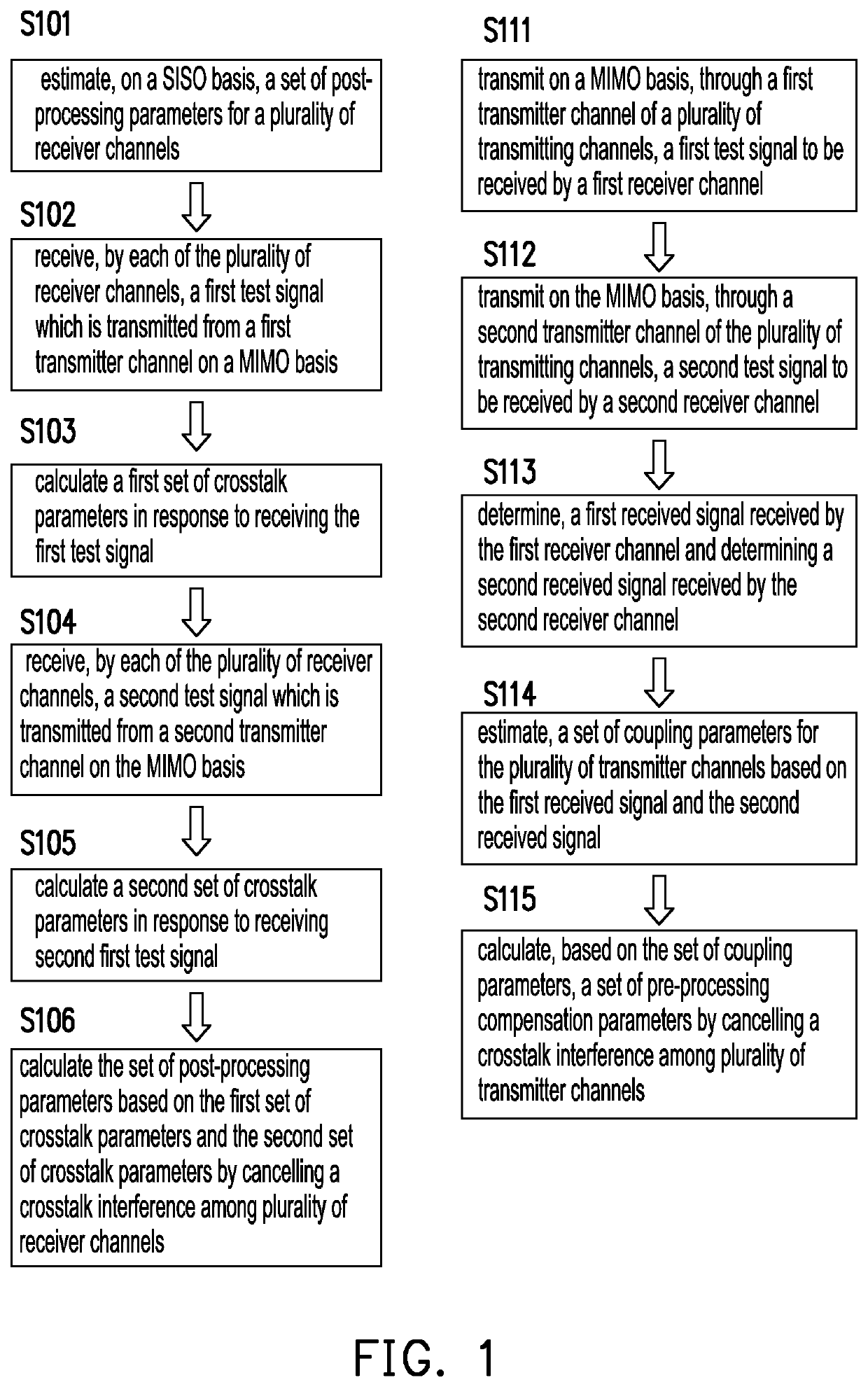
In aspect, the disclosure includes a method of configuring a MIMO wideband receiver. The method would include estimating, on a SISO basis, a set of post-processing parameters for a plurality of receiver channels; receiving, by each of the plurality of receiver channels, a first test signal which is transmitted from a first transmitter channel on a MIMO basis; calculating a first set of crosstalk parameters in response to receiving the first test signal; receiving, by each of the plurality of receiver channels, a second test signal which is transmitted from a second transmitter channel on the MIMO basis; calculating a second set of crosstalk parameters in response to receiving second test signal; and calculating the set of post-processing parameters based on the first set of crosstalk parameters and the second set of crosstalk parameters by cancelling a crosstalk interference among plurality of receiver channels.

Description

CROSS-REFERENCE TO RELATED APPLICATION[0001]This application claims the priority benefit of U.S. provisional application Ser. No. 62 / 872,251, filed on Jul. 10, 2019. The entirety of the above-mentioned patent application is hereby incorporated by reference herein and made a part of this specification.TECHNICAL FIELD[0002]The disclosure is directed to a method of configuring a MIMO wideband receiver, a method of configuring a MIMO wideband transmitter, and a MIMO wideband receiver using the same method, and a MIMO wideband transmitter using the same method.BACKGROUND[0003]Currently, the multi-antenna technology aims to achieve a high level of spectral efficiency so as to be utilized by the latest wireless communication system such as the 5G communication system which is under development. The 5G communication system may use a large number of multi-antenna systems which would combine multiple radio frequency (RF) transmitters and receivers (i.e. transceivers). However, when RF compone...

Claims


Application Information

Patent Timeline
IPC IPC(8): H04B15/00H04B7/0456H04B17/00H04B10/556
CPCH04B15/005H04B10/5561H04B17/0085H04B7/0456H04B7/0413H04B7/06H04B7/08H04B17/15H04B17/29
Inventor DENG, JUINN-HORNGCHEN, PIN-NIEN
Owner IND TECH RES INST
Learn More