
Blade angle position feedback system with magnetic shield

Active Publication Date: 2021-01-21
PRATT & WHITNEY CANADA CORP
View PDF0 Cites 1 Cited by
  • Summary
  • Abstract
  • Description
  • Claims
  • Application Information

AI Technical Summary

Benefits of technology

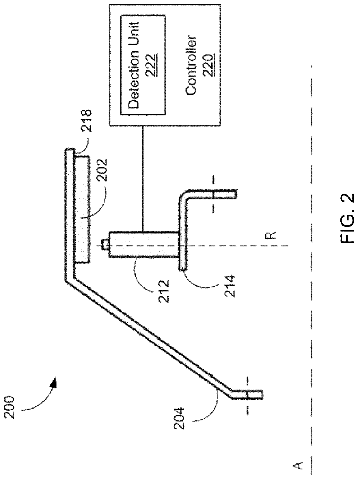
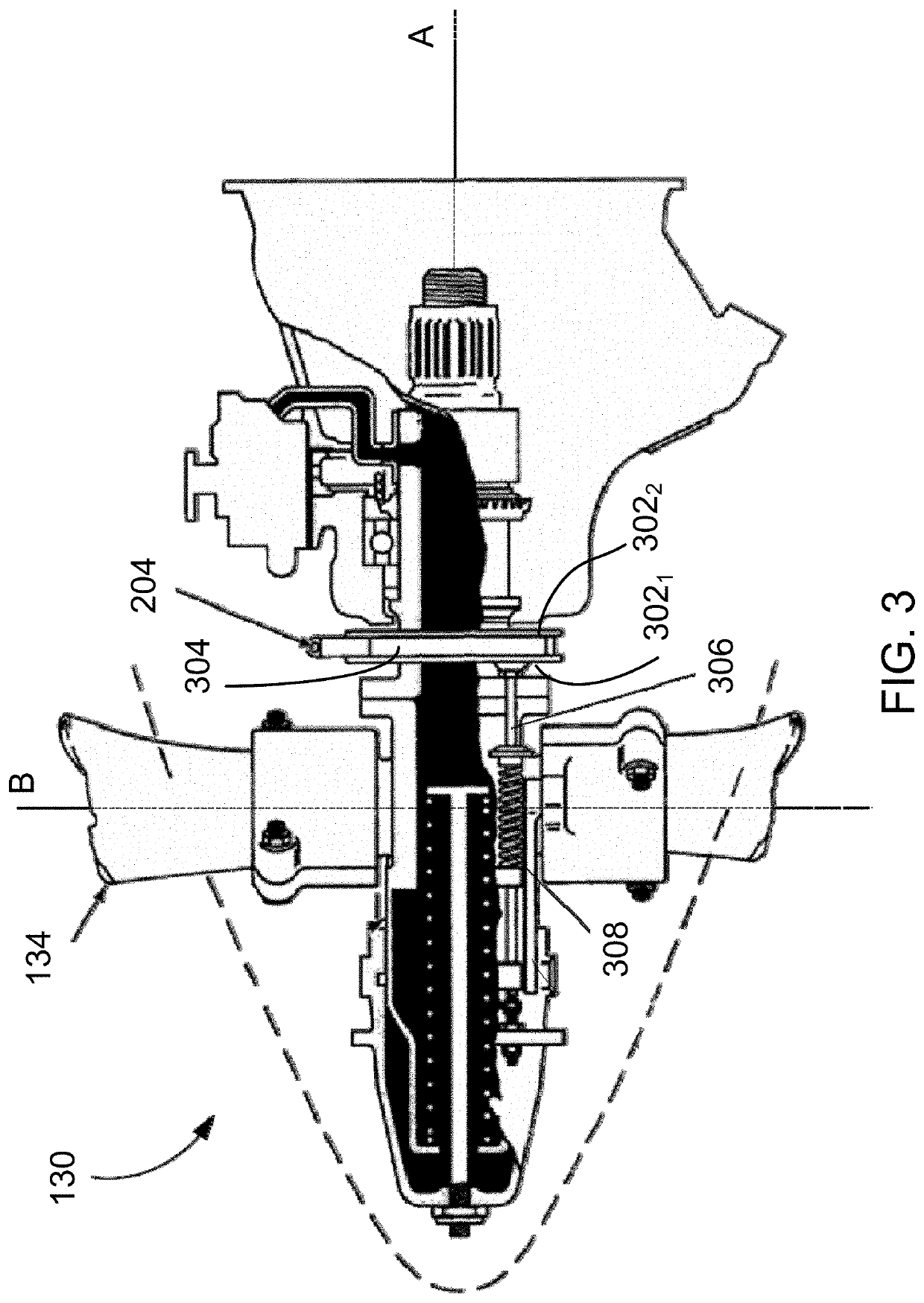
The patent describes a blade angle feedback assembly for a variable-pitch aircraft propeller rotor. The assembly includes a feedback device that rotates with the rotor and has a position marker that is displaced axially along the axis as the blade pitch angle of the rotor changes. The feedback device also has a sensor that detects the position marker as it passes by. The sensor is a magnet and a coil, with a magnetic shield that defines a magnetic return path for the magnetic flux. The technical effect of this assembly is that it provides accurate feedback on the blade angle of the rotor, allowing for precise control of the blade pitch angle.

Problems solved by technology

Existing feedback devices are however vulnerable to a so-called “edge-effect” that leads to an increase in reading error as the sensor approaches the edges of the feedback device.

Method used


Image

  • Blade angle position feedback system with magnetic shield
  • Blade angle position feedback system with magnetic shield
  • Blade angle position feedback system with magnetic shield

Examples


Embodiment Construction

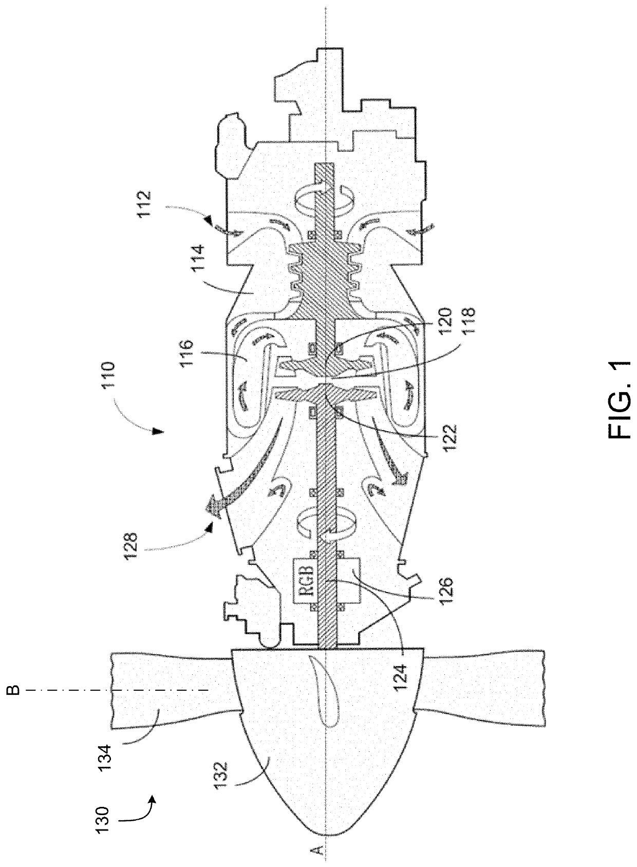
[0037]FIG. 1 depicts a gas turbine engine 110 of a type typically provided for use in subsonic flight. The engine 110 comprises an inlet 112 through which ambient air is propelled, a compressor section 114 for pressurizing the air, a combustor 116 in which the compressed air is mixed with fuel and ignited for generating an annular stream of hot combustion gases, and a turbine section 118 for extracting energy from the combustion gases.

[0038]The turbine section 118 comprises a compressor turbine 120, which drives the compressor assembly and accessories, and at least one power or free turbine 122, which is independent from the compressor turbine 120 and rotatingly drives a rotor shaft (also referred to herein as a propeller shaft or an output shaft) 124 about a propeller shaft axis ‘A’ through a reduction gearbox (RGB) 126. Rotation of the output shaft 124 is facilitated by one or more bearing assemblies (not illustrated), which can be disposed within the RGB 126 or at any other suita...


PUM


Abstract

A blade angle feedback assembly for a variable-pitch aircraft propeller rotor rotatable about an axis and having an adjustable blade pitch angle is provided. A feedback device is coupled to rotate with the rotor and to be displaced axially along the axis with adjustment of the blade pitch angle. Sensor(s) mounted adjacent the feedback device are configured to detect a passage of position marker(s) provided on the feedback device as the feedback device rotates. A magnetic shield mounted to the sensor(s) is configured to define a magnetic return path for some magnetic flux of a magnetic field exiting from a first pole of the magnet toward a second pole opposite the first pole. The magnetic shield comprises a wall member positioned adjacent the position marker(s) and configured to span a distance over which the position marker(s) are configured to be displaced with axial displacement of the feedback device.

Description

TECHNICAL FIELD[0001]The present disclosure relates generally to variable-pitch propellers for aircraft, and more specifically to blade angle position feedback systems.BACKGROUND OF THE ART[0002]On featherable aircraft propeller systems, it is desirable to accurately measure the propeller blade pitch (or beta) angle to ensure that the blade angle is controlled according to the engine power set-point requested, such as in reverse and low pitch situations, also known as the beta operating region. For this purpose, some propeller feedback systems use a beta or feedback device, sometimes referred to as a phonic wheel, which rotates with the engine. The feedback device has multiple readable markers and a sensor can be used to measure the rotation of the feedback device via the markers, providing a proxy value for the rotational velocity of the engine, as well as measure blade angle. Existing feedback devices are however vulnerable to a so-called “edge-effect” that leads to an increase in...

Claims


Application Information

Patent Timeline
IPC IPC(8): B64C11/06G01B7/30
CPCB64C11/06G01R33/038G01B7/30B64C11/301G01D5/147G01P3/488
Inventor TOMESCU, DANA
Owner PRATT & WHITNEY CANADA CORP
Learn More