
MEMS force balance accelerometer

a technology of force balance and accelerometer, which is applied in the direction of speed/acceleration/shock measurement, measurement devices, instruments, etc., can solve the problems of high scale factor and performance degradation, and achieve the effect of improving sensitivity, reducing power requirements, and reducing signal to noise ratio

Active Publication Date: 2011-08-16
HONEYWELL INT INC
View PDF19 Cites 3 Cited by
  • Summary
  • Abstract
  • Description
  • Claims
  • Application Information

AI Technical Summary

Benefits of technology

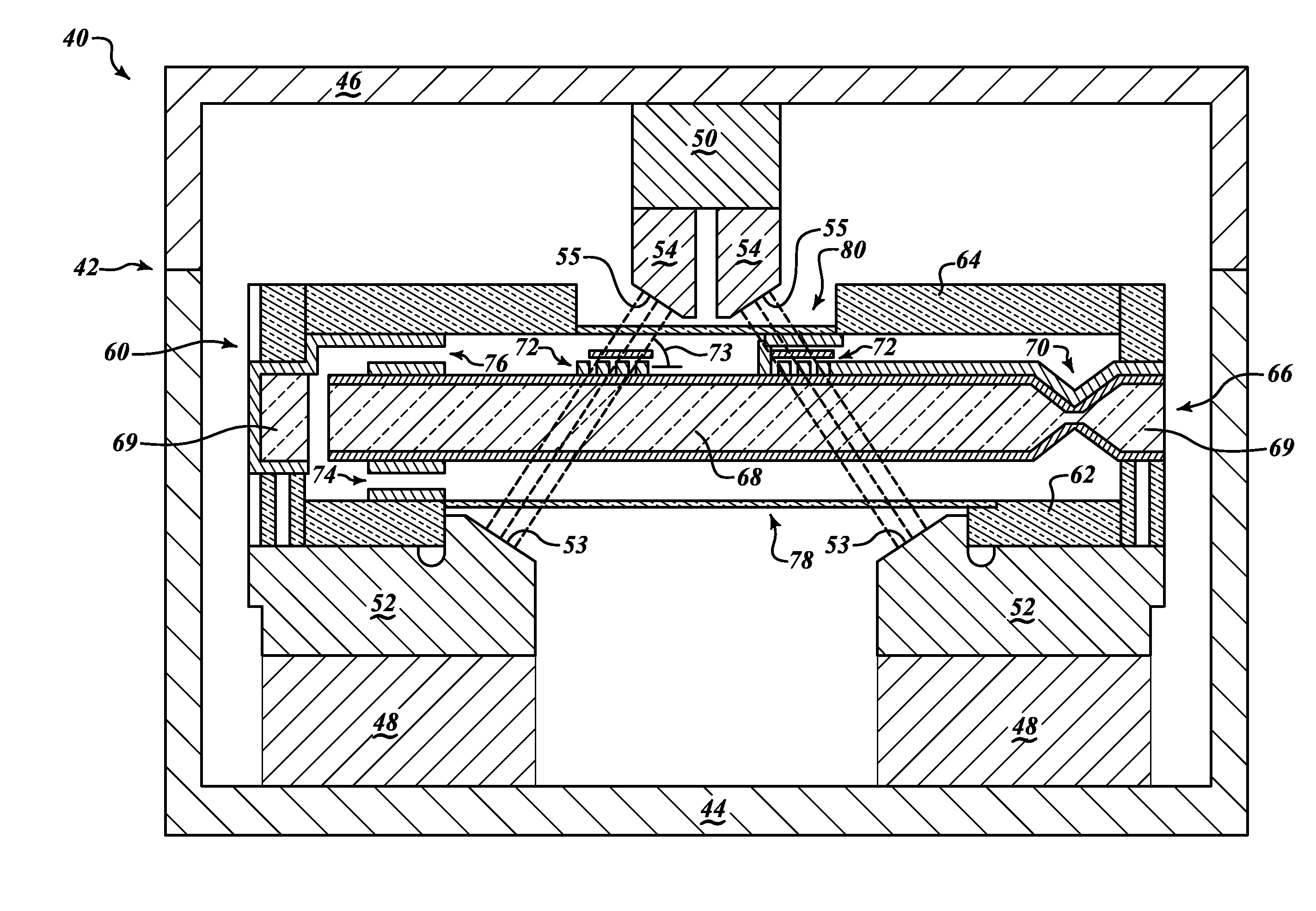
The present invention is a system a microelectromechanical (MEMS) accelerometer and acceleration sensing methods having improved sensitivity, a greater signal to noise ratio, and lower power requirements. An example MEMS accelerometer includes a proof mass suspended by at least one flexure, a planar coil on the proof mass, at least one magnet, a first pole piece positioned proximate a first side of the proof mass, and a second pole piece positioned proximate a second side of the proof mass. A magnetic flux field passes from at least one of the at least one magnets, through the first pole piece, through the planar coil at a flux angle between approximately 30 degrees and approximately 60 degrees relative to the coil plane, and into the second pole piece. In an example embodiment, the flux angle is approximately 45 degrees. A method includes sensing a capacitance of a pickoff in the MEMS accelerometer and rebalancing the MEMS accelerometer by sending a current through the planar coil.
In accordance with still further aspects of the invention, the MEMS accelerometer further includes a first housing layer positioned on a first side of the proof mass and a second housing layer positioned on a second side of the proof mass. The first housing layer defines a first recessed area and the second housing layer defines a second recessed area. The first pole piece extends at least partially into the first recessed area and the second pole piece extends at least partially into the second recessed area. The first and second recessed areas allow the first and second pole pieces to have a smaller gap between them, which results in a lower reluctance for a magnetic circuit that passes through the coil on the proof mass.

Problems solved by technology

A gap in the magnetic return path with this configuration is defined by a diameter of the coil, and is thus relatively large with a corresponding large reluctance of the magnetic circuit which results in a high scale factor.
This type of coil configuration requires a level of current to servo the accelerometer that generates heating effects that create nonlinearities which degrade performance.

Method used


Image

  • MEMS force balance accelerometer
  • MEMS force balance accelerometer
  • MEMS force balance accelerometer

Examples


Embodiment Construction

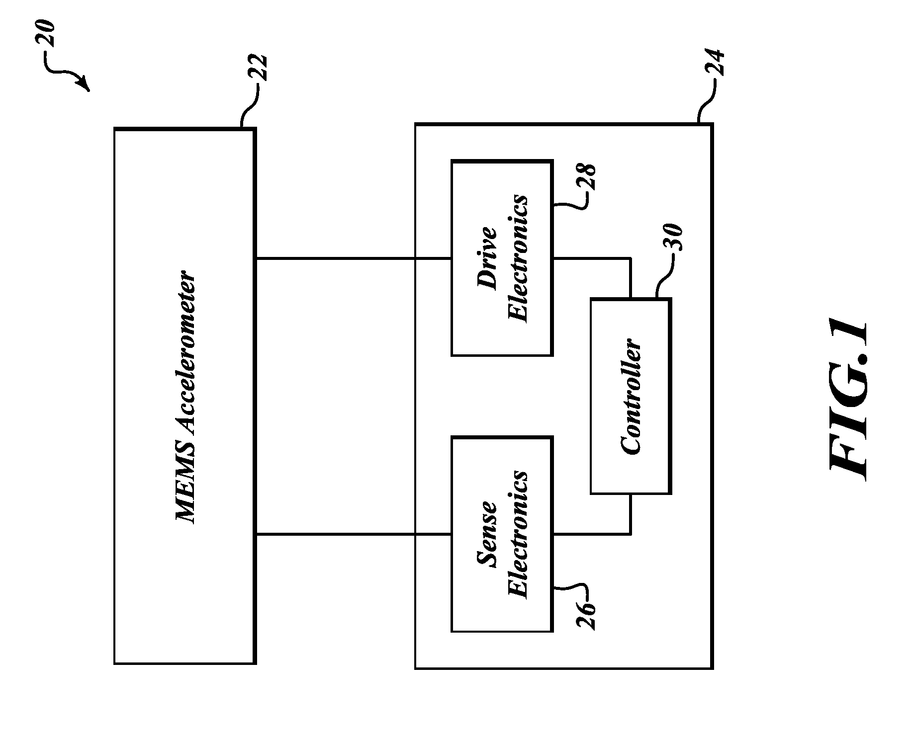
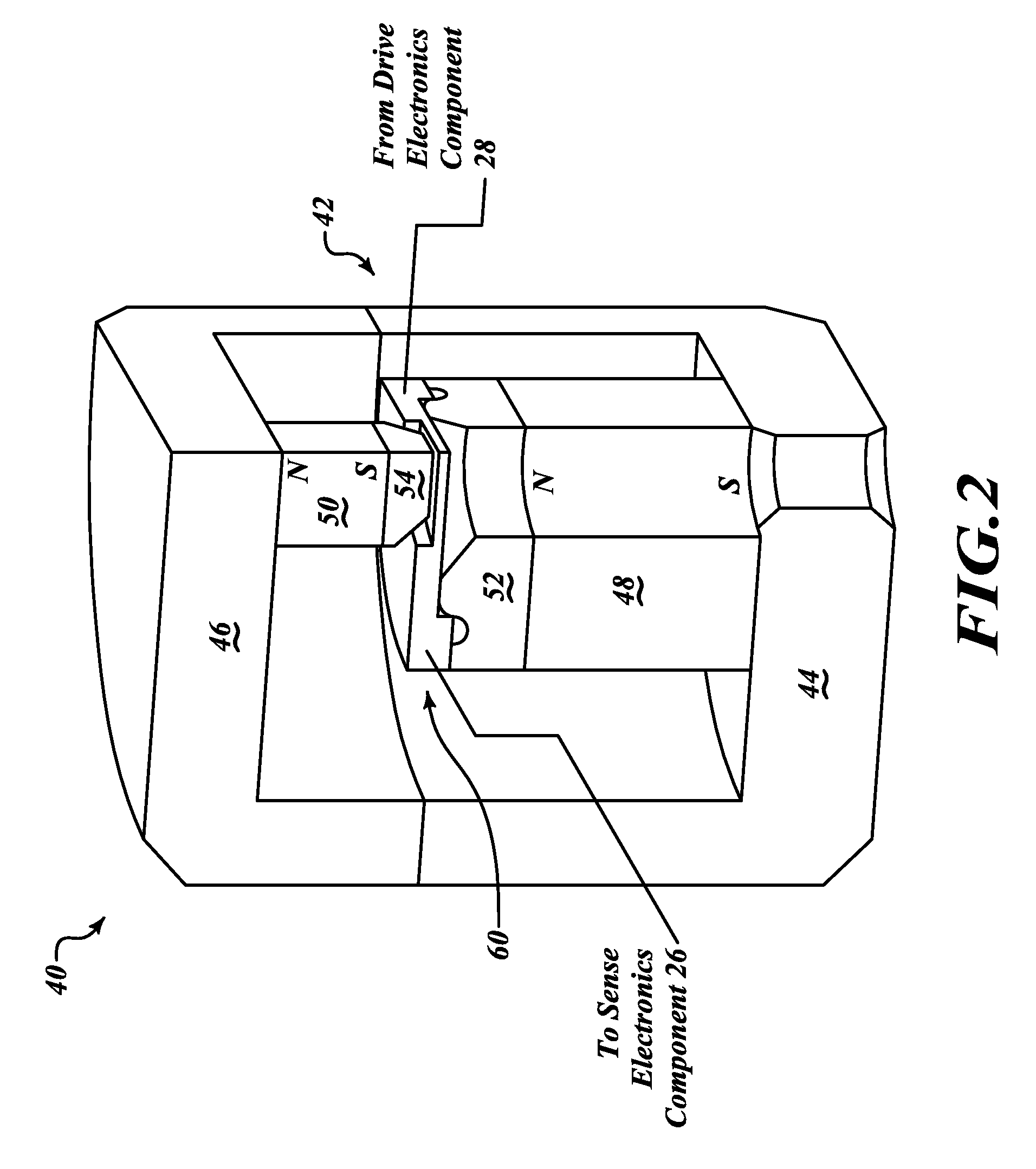
FIG. 1 is a block diagram of a microelectromechanical (MEMS) accelerometer system 20 formed in accordance with an embodiment of the invention. The MEMS accelerometer system 20 includes an accelerometer 22 and a control unit 24. The control unit 24 includes a sense electronics component 26 and a drive electronics component 28, both in signal communication with the MEMS accelerometer 22. The control unit 24 also includes a controller 30 in signal communication with the sense electronics component 26 and the drive electronics component 28. Generally, the accelerometer 22 includes a proof mass suspended by at least one flexure within a housing and a magnetic rebalancing component for rebalancing the proof mass about the at least one flexure. The magnetic rebalancing component includes at least one magnet, at least one pole piece, and a magnetic return path structure. The magnetic rebalancing component servo actuates the accelerometer 22 by passing a current through at least one planar c...


PUM


Abstract

Microelectromechanical (MEMS) accelerometer and acceleration sensing methods. A MEMS accelerometer includes a proof mass, a planar coil on the proof mass, a magnet, a first pole piece positioned proximate a first side of the proof mass, and a second pole piece positioned proximate a second side of the proof mass. A magnetic flux field passes from the magnet, through the first pole piece, through the planar coil at an angle between approximately 30 degrees and approximately 60 degrees relative to the coil plane, and into the second pole piece. The first pole piece may extend into a first recessed area of a first housing layer and the second pole piece may extend into a second recessed area of a second housing layer. A method includes sensing a capacitance of a pickoff in the MEMS accelerometer and rebalancing the MEMS accelerometer by sending a current through the planar coil.

Description

BACKGROUND OF THE INVENTIONTypical configurations for force balance microelectromechanical (MEMS) accelerometers that have a proof mass with a coil have a magnetic circuit configuration with a large reluctance value. Generally, previous coil and magnetic circuit configurations are structured such that a magnetic field runs parallel with the plane of a spiral coil. The magnetic field excites a return path that penetrates a proof mass using holes. A gap in the magnetic return path with this configuration is defined by a diameter of the coil, and is thus relatively large with a corresponding large reluctance of the magnetic circuit which results in a high scale factor. This type of coil configuration requires a level of current to servo the accelerometer that generates heating effects that create nonlinearities which degrade performance.SUMMARY OF THE INVENTIONThe present invention is a system a microelectromechanical (MEMS) accelerometer and acceleration sensing methods having improve...

Claims


Application Information

Patent Timeline
Patent Type & Authority Patents(United States)
IPC IPC(8): G01P15/08
CPCG01P15/132
Inventor DWYER, PAUL W.ROEHNELT, RYAN
Owner HONEYWELL INT INC
Learn More