Permanent magnet induction generator (PMIG)

a permanent magnet induction and generator technology, applied in the direction of variable transformers, inductances, variable inductances, etc., can solve the problems of flux bleed-through of resistance switches, and achieve the effects of low resistance, high magnetic permeability, and increased or decreased permeability

Active Publication Date: 2018-06-07
ANNIS THEODORE C
View PDF6 Cites 2 Cited by
  • Summary
  • Abstract
  • Description
  • Claims
  • Application Information

AI Technical Summary

Benefits of technology

[0014]The preferred apparatus includes three magentizeable members, each having first and second ends, including a first member, a central member, and a second member. Four reluctance switches are provided, including a first switch between the first ends of the first and central members, a second switch between the second ends of the first and central members, a third switch between the first ends of the central and second members, and a fourth switch between the second ends of the central and second members.
[0015]The apparatus further includes a contiguous loop of magnetizable material. At least one permanent magnet has a first pole coupled to a first point of the loop and a second pole coupled to the first magentizeable member. Another permanent magnet has a first pole coupled to the second magentizeable member and a second pole coupled to an opposing point of the loop, whereby the first poles of both magnets are north, and the second poles of both magnets are south poles, or vice versa.
[0016]At least one loop of electrically conductive material such as wire is wound around the central magnetizeable member between the first and second ends thereof, and an electrical control unit operative to drive the reluctance switches at a switching frequency such that flux from the permanent magnets reverses in the central magentizeable member, thereby inducing electrical energy in the loop of electrically conductive material.
[0017]In the preferred embodiments, the magnetizable members and the loop of magnetizeable material exhibit a high magnetic permeability (low reluctance). The switching frequency may be between 1 Hz and 100,000 Hz, or more preferably between 50 Hz and 10,000 Hz.
[0018]The reluctance switches may be implemented by applying an electric current to cause electromagnetic induction to magnetically saturate a section of the magnetic path to create a region of high reluctance (on-condition to an off-condition), or to magnetically un-saturate a section of the magnetic path that is already saturated by the use of a permanent magnet (off-condition to an on-condition). Alternatively, the reluctance switches may be composed of a material that changes reluctance under the influence of an external stimulus such as an electric field, heat, or pressure. As a further alternative, the reluctance switches may be composed of a ferrofluidic material, in which case the switching circuitry may be operative to activate the switches applying heat to the ferrofluid via microwave energy or by heating a material surrounding the ferrofluid. As yet a different alternative, the reluctance switches composed of materials which change their crystal structure under the influence of an electric field or pressure such that the crystalline magnetic anisotropy constant changes and the permeability increases or decreases.
[0019]In any case, the reluctance switches change relative magnetic permeability from a value of between 1 and 10 to a value between 20 and one million, or vice versa, in response to the electrical control unit or, more preferably, between 1 and 3 to a value between 4 and one million, or vice versa, in response to the electrical control unit.

Problems solved by technology

With the current state of the art, reluctance switches often have flux bleed-through.

Method used


Image

  • Permanent magnet induction generator (PMIG)
  • Permanent magnet induction generator (PMIG)
  • Permanent magnet induction generator (PMIG)

Examples


Embodiment Construction

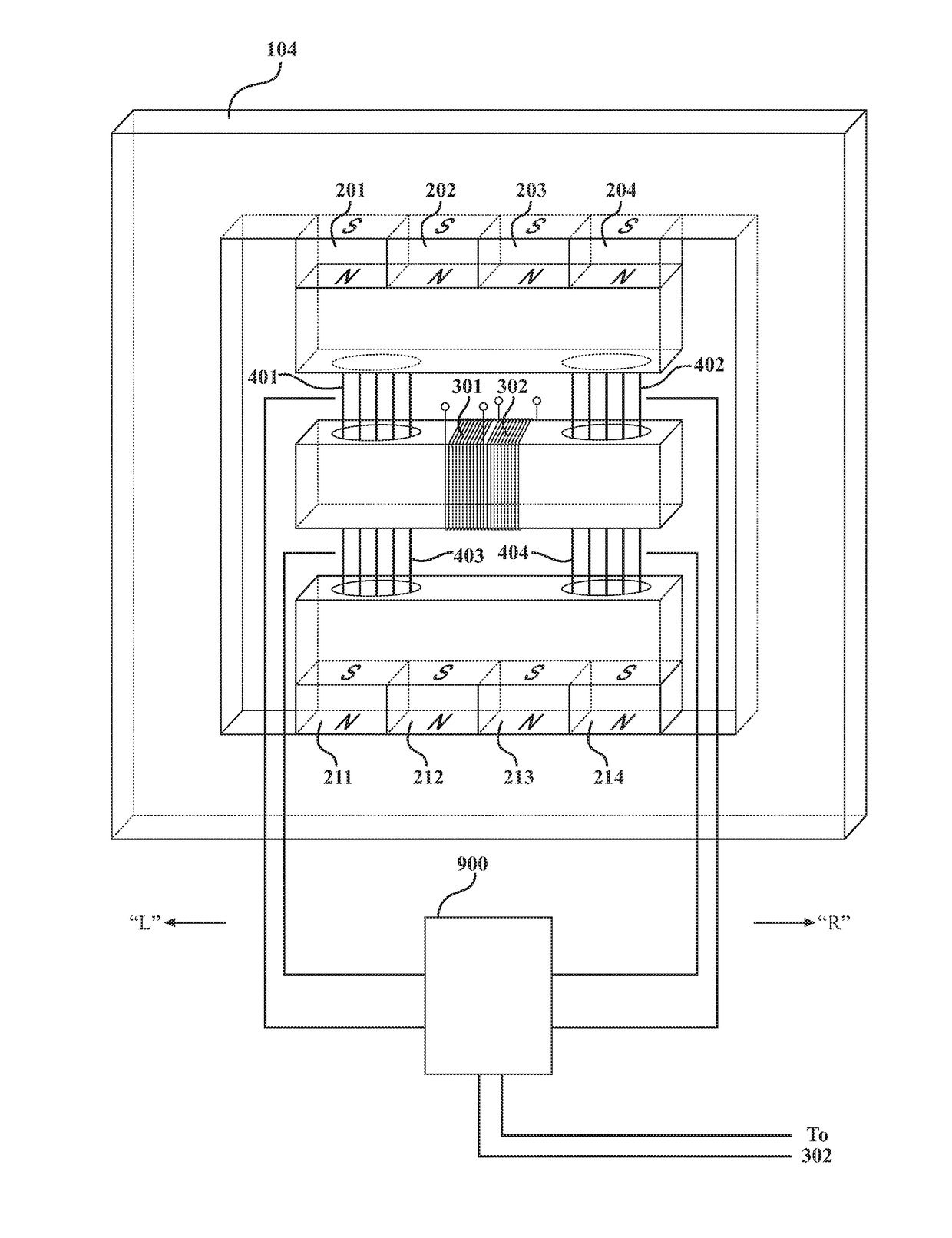
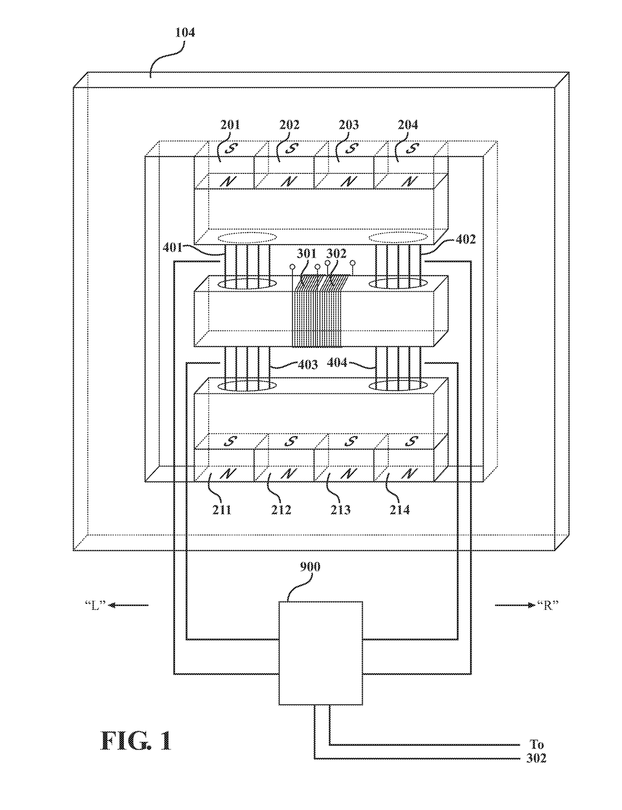
[0029]A preferred embodiment of the invention is illustrated in FIG. 1. “Right” and “left” orientations are shown in the figure with the understanding that these are arbitrary and for the purposes of description. The apparatus includes three magnetizable members, 101, 102, 103, defining a first region, a central region, and a second region, respectively. These magnetizable members have right and left ends. Around the central region there is wound an electrical conductor such as a coil or coils of wire, 301 and 302.

[0030]A contiguous backbone member of magnetizable material, 104, provides magnetic continuity for first and second sets of permanent magnets. A first magnet or set of permanent magnets, arranged in parallel at 201-204, that have their south pole(s) in contact with backbone member 104 and north pole(s) in contact with the first magnetizable member, 101. A second magnet or set of permanent magnets, 211-214, have a south pole in contact with the second magnetizable material ...


PUM

PropertyMeasurementUnit
switching frequencyaaaaaaaaaa

Abstract

Conversion of magnetic flux energy into electrical power with a permanent magnet induction generator (PMIG) comprised of permanent magnets, a magnetic circuit, reluctance switches (magnetic flux switches), and a switching sequence performed by an electrical controller that causes the flux from two opposing, magnetically aligned permanent magnets to be repeatedly alternated through a single flux path for the purpose of generating AC electricity. Energy efficient reluctance switches operation permits the output electrical energy to exceed the energy required to operate them thereby enabling continuous operation that produces uninterrupted electricity without the need for fuel or external energy input.

Description

REFERENCE TO RELATED APPLICATIONS[0001]This application claims priority to U.S. Provisional Patent Application Ser. No. 62 / 431,123, filed Dec. 7, 2016, the entire content of which is incorporated herein by reference.FIELD OF THE INVENTION[0002]This invention relates generally to the conversion of energy into power and, in particular, to a device operative to convert magnetic flux energy into electrical power.BACKGROUND OF THE INVENTION[0003]The physics related to electromagnetic induction within an inductor and a transformer is described by Faraday's transformer equation:ɛ=-dBdt[0004]According to Moskowitz, “Permanent Magnet Design and Application Handbook” 1995, p 52, magnetic flux may be thought of as flux lines which always leave and enter the surfaces of ferromagnetic materials at right angles, which never can make true right-angle turns, which travel in straight or curved paths, which follow the shortest distance, and which follow the path of lowest reluctance. Hopkinson's Law ...

Claims


Application Information

Patent Timeline
Patent Type & Authority Applications(United States)
IPC IPC(8): H01F29/14H01F38/08
CPCH01F29/14H01F38/08H02N11/008Y10S74/09
Inventor ANNIS, THEODORE C.
Owner ANNIS THEODORE C
Why Eureka
Try Eureka