Fault current limiter

a current limiter and fault technology, applied in the field of fault current limiters, can solve the problems of high dynamical and thermal stress on equipment, inability to avoid faults in electrical power systems, and conventional circuit breaker technology does not provide a full solution to selective interrupting currents. performance improvement

Active Publication Date: 2016-11-29
GRIDON
View PDF39 Cites 0 Cited by
  • Summary
  • Abstract
  • Description
  • Claims
  • Application Information

AI Technical Summary

Benefits of technology

[0009]The present invention sets out to provide an FCL with improved performance compared to conventional arrangements.
[0014]Such embodiments are associated with improved fault to normal state impedance ratio, as a result of the closed AC magnetic circuit. This ensures that increase of impedance from normal to short circuit state is controlled by the core saturation alone instead of combined core-air magnetic path in some conventional arrangements. This provides a controlled increase of impedance in short circuit state, and high impedance ratios (typically well above 5) can be achieved without large increase of AC ampere turns.
[0015]In other words, having a closed AC magnetic path is beneficial from the point of view of achieving lower reluctance, with higher impedance than for conventional designs (that use, for example, a combined core-air magnetic path in an open circuit AC design). Furthermore, having a closed magnetic path for the DC magnetic circuits is also beneficial, as it reduces DC ampere-turns and reduces DC flux outside the FCL.
[0016]The first, second, third and fourth legs of the core may be orientated in the same direction. For example, the first, second, third and fourth legs may be arranged vertically. Arranging the legs vertically has the advantage that, from a manufacturing perspective, it is easier to assemble the core and coils when compared to conventional FCLs that use coils wound around horizontal legs. For example, horizontally laid DC coils in conventional FCLs have to be supported in air, and core laminations threaded through the coils, a few laminations at a time. This is slow and relatively unsafe during manufacturing.
[0018]In other words, using vertically oriented windings provides a natural thermo-siphon effect and higher thermal head for oil flow through windings. Stagnant oil in horizontally oriented winding of conventional arrangements is prevented, winding temperature is reduced and hot spots are minimized.

Problems solved by technology

Faults in electrical power systems cannot be avoided.
Fault currents flowing from the sources to a location of the fault lead to high dynamical and thermal stresses being imposed on equipment e.g. overhead lines, cables, transformers and switch gears.
Conventional circuit breaker technology does not provide a full solution to selectively interrupting currents associated with such faults.
The growth in electrical energy generation and consumption and the increased interconnection between networks leads to increasing levels of fault current.
In particular, the continuous growth of electrical energy generation has the consequence that networks reach or even exceed the limits with respect to their short circuit withstand capability.
These may result in power disruptions, equipment damage and major outages, which have been estimated to cost billions of dollars per year.
In order to restrict fault current impact, utility operators have traditionally needed to resort to network segmentation and installation of expensive and lossy protection gear, such as series reactors, capacitors, high rated circuit breakers and high impedance transformers.
Such solutions come at the cost of overall reduction of energy efficiency and network stability.
In a fault condition (e.g. a short-circuit), a current surge will increase the current on the AC coil, causing desaturation of the ion core.

Method used


Image

  • Fault current limiter
  • Fault current limiter
  • Fault current limiter

Examples


first embodiment

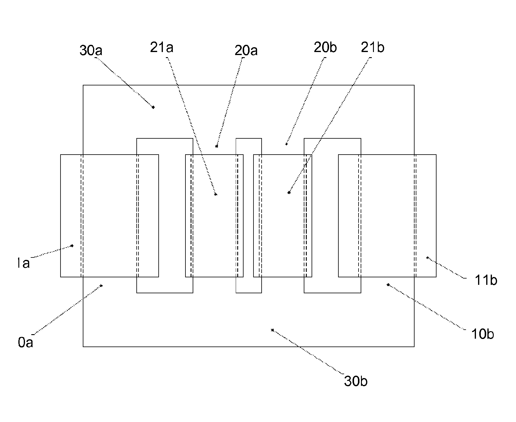
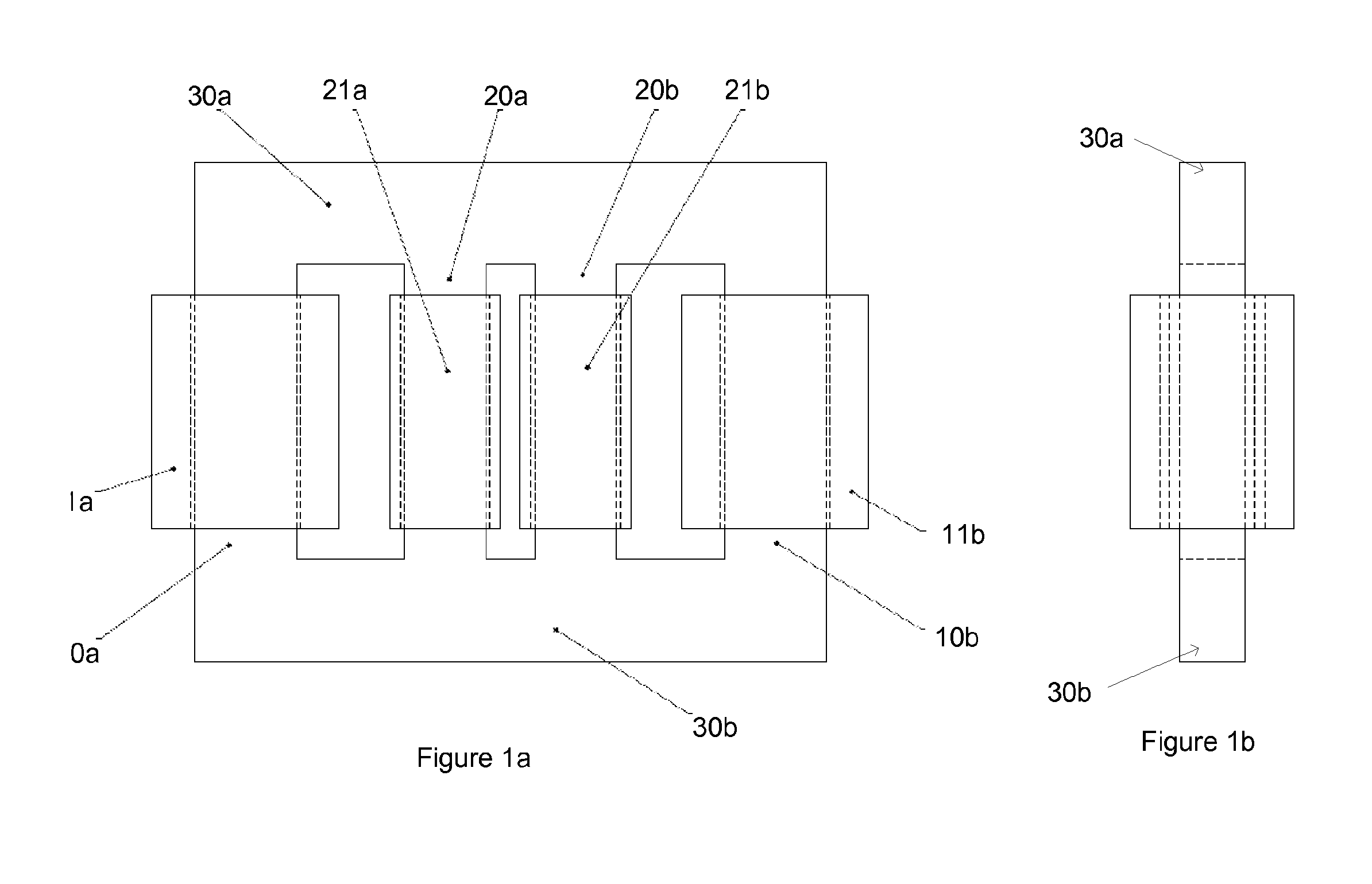
[0048]FIGS. 1a and 1b show the invention. In this embodiment, the FCL 1 has a single core, and the FCL 1 is arranged to limit fault currents for a single phase AC supply. FIG. 1a shows a side view, whereas FIG. 1b shows an end view.

[0049]As shown in FIG. 1a, the FCL 1 has a single core that includes four legs 10a, 20a, 20b and 10b aligned in the same direction. The four legs are joined by a first yoke 30a at one end, and by a second yoke 30b at the other end. In this embodiment, the four legs 10a, 20a, 20b and 10b are aligned vertically, with the two yokes 30a, 30b aligned horizontally.

[0050]A first DC coil 11a is wound around the first leg 10a, and a second DC coil 11b is wound around the fourth leg 10b. Hence, a DC coil is wound around each of the two outer legs 10a and 10b.

[0051]A first AC coil 21a is wound around the second leg 20a, and a second AC coil 21b is wound around the third leg 20b. The AC coils 21a and 21b are connected in series, and are connected to the grid. Hence,...

second embodiment

[0125]The FCL 100 of the second embodiment can further comprise a tank (not shown) arranged to house the core. The tank can be partially or completely filled with a dielectric fluid. Any suitable dielectric fluid could be used, for example mineral oil.

[0126]In the FCL 100 of the second embodiment, the first 121Ra, third 121Sa and fifth 121Ta AC coils are arranged from top to bottom in order on the second leg 120a, and the sixth 121Tb, fourth 121Sb and second 121Rb AC coils are arranged top to bottom in order on the third 120b leg. However, in other embodiments, the R, S, T coils on each leg may be arranged in a different pattern. For example, in some embodiments, the first 121Ra, third 121Sa and fifth 121Ta AC coils may be arranged in order on the second leg 120a, and the sixth 121Tb, fourth 121Sb and second 121Rb AC coils may be arranged in the same order on the third 120b leg.

[0127]In some embodiments that use three AC coils (one of each phase) on a single core, the AC coils for e...


PUM

PropertyMeasurementUnit
voltagesaaaaaaaaaa
timeaaaaaaaaaa
DC currentaaaaaaaaaa

Abstract

A fault current limiter is provided that comprises a magnetically saturable core. The first core includes a first leg, a second leg, with a first AC coil wound on the second leg, a third leg, with a second AC coil wound around the third leg, the first and second AC coils being wound in series and connected to a first phase AC source, and a fourth leg. The first magnetic biasing unit is arranged to produce a first closed magnetic circuit in the first leg and the second leg that has a first flux direction, and the second coil is arranged to produce a second closed magnetic circuit in the fourth leg and the third leg that has a second flux direction, wherein the first flux direction opposes the second flux direction. The first and second AC coils are arranged to produce a first closed AC magnetic circuit in the second and third legs in an AC flux direction that alternates with each AC half-cycle.

Description

CROSS-REFERENCE TO RELATED APPLICATION[0001]This application is a national phase filing, under 35 U.S.C. §371(c), of International Application No. PCT / IB2012 / 054196, filed Aug. 17, 2012, with claim of priority to United Kingdom Patent Application No. 1114277.5, filed in the United Kingdom Patent Office on Aug. 18, 2011, the disclosures of which are incorporated herein by reference in their entirety.FIELD OF THE INVENTION[0002]The present invention relates to a fault current limiter (FCL).BACKGROUND OF THE INVENTION[0003]Faults in electrical power systems cannot be avoided. Fault currents flowing from the sources to a location of the fault lead to high dynamical and thermal stresses being imposed on equipment e.g. overhead lines, cables, transformers and switch gears.[0004]Conventional circuit breaker technology does not provide a full solution to selectively interrupting currents associated with such faults. The growth in electrical energy generation and consumption and the increase...

Claims


Application Information

Patent Timeline
Patent Type & Authority Patents(United States)
IPC IPC(8): H02H7/00H02H9/02H01F38/02H01F29/14H01F6/00H02H3/33H01F3/10
CPCH02H9/021H01F29/14H01F38/023H01F2003/103H01F2006/001H02H3/332H01F3/00H01F3/10
Inventor WILSON, ROBERTPANNU, MOHINDER
Owner GRIDON
Why Eureka
Try Eureka