Stator for an electric motor and cooling thereof

a technology of electric motors and rotors, which is applied in the direction of cooling/ventilation arrangement, magnetic circuit rotating parts, and shape/form/construction of magnetic circuits, etc., can solve the problems of limited power rating and efficiency of motors such as dc brushless motors, and achieve the effect of enhancing the extraction of heat from magnets and impedeing the conduction of hea

Active Publication Date: 2021-01-21
EQUIPMAKE +1
View PDF11 Cites 1 Cited by
  • Summary
  • Abstract
  • Description
  • Claims
  • Application Information

AI Technical Summary

Benefits of technology

[0010]Such a configuration enables different fluids to be used for cooling the stator and the rotor, respectively. Preferably, a liquid is used to cool the stator. Air may be used, for example, to cool the rotor. With the cooling fluid able to pass directly over the stator coils, instead of having another component such as a stator support or casing between the coils and the fluid, it is possible to take heat away from the coils at a significantly higher rate. The ability to remove heat from the coils more effectively allows higher current densities to be used, resulting in a smaller motor for a given output.
[0019]This enables a motor including the stator to be made more compact. With the fluid paths passing over the support substantially parallel to the axial direction, axially extending rods or bolts used to hold the motor together can be located circumferentially between adjacent sections of the fluid path at a similar distance from the motor axis. This is in contrast to known motor configurations in which the fluid paths extend over the support in a helical configuration, requiring supporting bolts to be provided radially outwardly from the cooling paths, thereby increasing the overall diameter of the motor.
[0021]The coils may include a thermally conductive covering material, either over each strand individually, or covering the wound coils. This covering serves to protect the coils and assist the extraction of heat from the coils.
[0028]In some known rotor configurations, the rotor segments and permanent magnets are retained on a hub by a sleeve. However, this impedes the conduction of heat away from the rotor. In the claimed arrangement, the rotor is constructed such that a radially outwardly facing surface of each magnet is exposed so that it can be in direct contact with a surrounding cooling fluid such as air. Furthermore, this exposed surface of each magnet is spaced radially inwardly from the outer circumference defined by the segments. This assists the circulation of the cooling fluid adjacent to the exposed surfaces, enhancing the extraction of heat from the magnets.

Problems solved by technology

The power rating and efficiency of motors such as DC brushless motors is largely limited by cooling considerations and the ability of the coils to carry current without overheating and melting.

Method used


Image

  • Stator for an electric motor and cooling thereof
  • Stator for an electric motor and cooling thereof
  • Stator for an electric motor and cooling thereof

Examples


Embodiment Construction

[0045]In the following discussion, some dimensions are given. It will be appreciated that these dimensions are merely given to provide examples of relative sizes and proportions of the features concerned, and may be varied and / or scaled to suit different requirements.

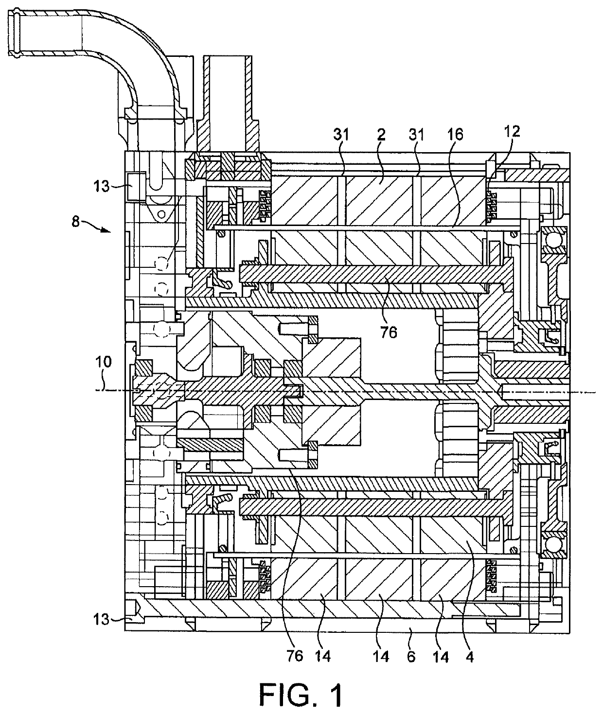
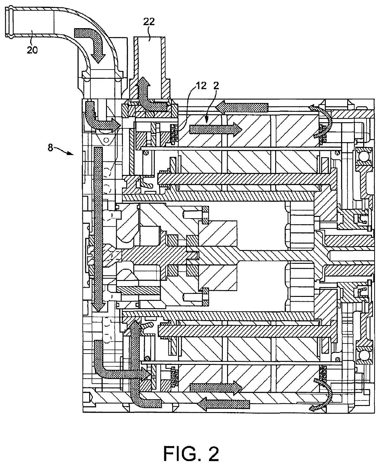
[0046]A longitudinal cross-sectional view of a motor including a stator configuration according to an embodiment of the present invention is shown in FIG. 1. A stator 2 and rotor 4 are located within the motor casing 6 of the motor 8. The rotor rotates about a central axis 10.

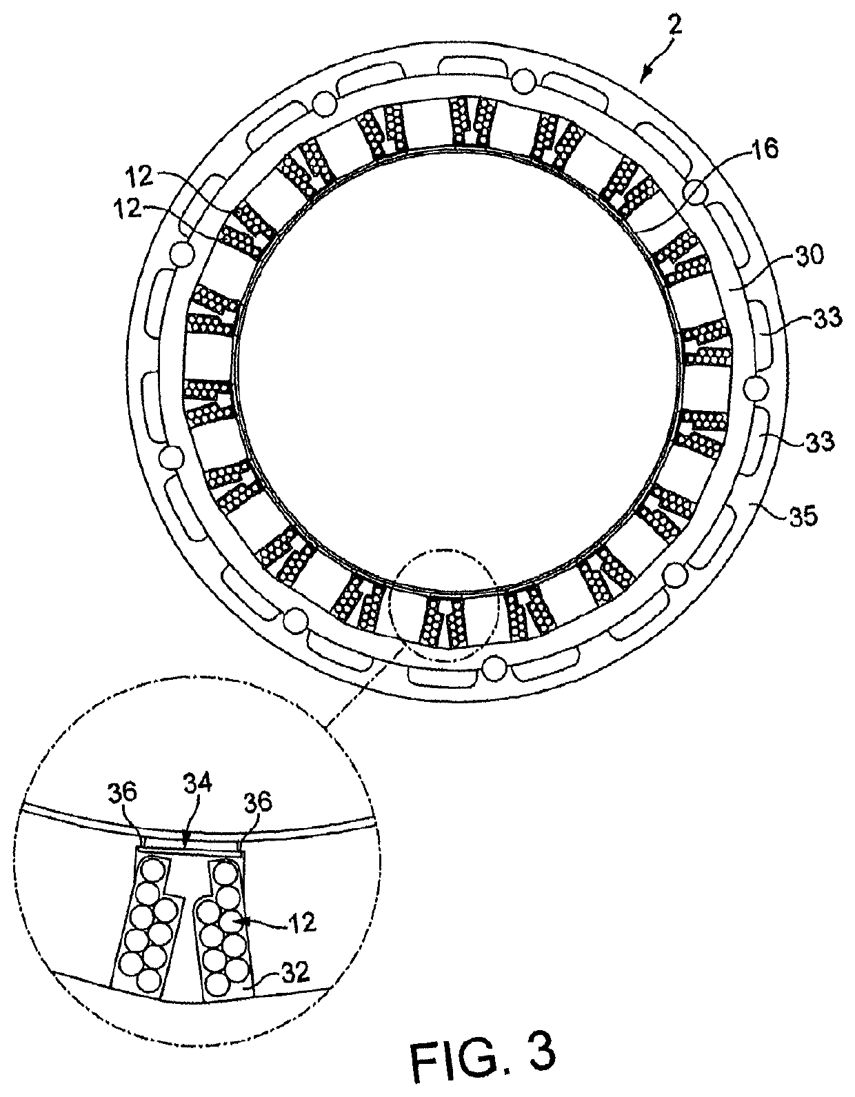
[0047]Stator coils 12 are elongated in the axial direction and extend around respective, circumferentially spaced segments 14 of a laminated stator core. The segments may be formed of silicon or cobalt steel or another material suitable for motor laminations.

[0048]A plurality of axially extending bolts 13 clamp the motor assembly together between end plates. They also transmit the reaction torque from the stator segments 14 to the motor casing 6 an...


PUM


Abstract

A stator and a rotor suitable for use in an electric motor or generator. The stator comprises a plurality of stator cons and a support for holding the coils around a rotor of the motor. A cylindrical sleeve is mounted radially inwardly on the support to form a barrier in use between cooling fluid passing over the coils and a rotor located within the stator. The rotor comprises a hub, a plurality of rotor segments, and a plurality of permanent magnets. The segments are arranged around the hub in a ring, with the permanent magnets disposed between the segments. A radially outwardly facing exposed surface of each magnet is spaced radially inwardly from an outer cylindrical profile defined by the segments.

Description

CROSS-REFERENCE TO RELATED APPLICATIONS[0001]The present application is a continuation of co-pending U.S. patent application Ser. No. 14 / 905,402, filed Jan. 15, 2016, which is a submission under 35 U.S.C. § 371 of International Application No. PCT / GB2014 / 052159, filed Jul. 15, 2014, which claims priority to Great Britain Application No. 1312678.4, filed Jul. 16, 2013, the disclosures of which are hereby expressly incorporated by reference herein in their entireties.FIELD OF THE INVENTION[0002]The present invention relates to a stator and a rotor suitable for use in an electric motor or generator. More particularly, it concerns the cooling of these components.BACKGROUND OF THE INVENTION[0003]Rotors for use in motors such as brushless DC motors include permanent magnets held within the rotor. Torque is applied by a rotating magnetic field. This is created by applying current, usually in three separate phases, to stationary coils mounted in an outer stator. This type of motor is becomi...

Claims


Application Information

Patent Timeline
Patent Type & Authority Applications(United States)
IPC IPC(8): H02K9/197H02K9/06H02K5/128H02K5/20H02K9/04H02K1/32H02K1/27H02K3/24
CPCH02K9/197H02K9/06H02K5/128H02K5/20H02K1/2773H02K1/32H02K1/274H02K3/24H02K2005/1287H02K9/04H02K5/203H02K5/207H02K1/20H02K1/278
Inventor SAKURAI, YOSHITOSHIFOLEY, IANOGILVIE, MARTINWILLIAMSON, ROBKAWAMOTO, MICHIO
Owner EQUIPMAKE
Why Eureka
Try Eureka