Surveying System
- Summary
- Abstract
- Description
- Claims
- Application Information
AI Technical Summary
Benefits of technology
Problems solved by technology
Method used
Image

Examples
first embodiment
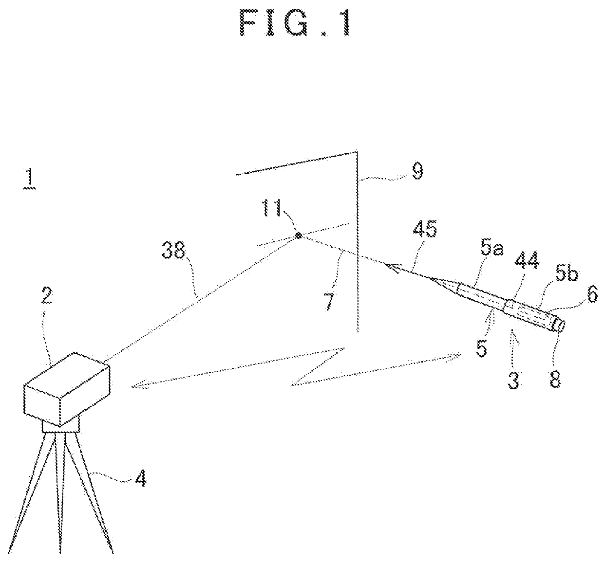
[0032]First, in FIG. 1, a description will be given on an outline of a surveying system according to the present invention.
[0033]A surveying system 1 has a surveying instrument 2 provided at an arbitrary position and a trigger device 3 having a trigger communication module 6 which can communicate with the surveying instrument 2. The surveying instrument 2 is, for instance, a laser scanner, and the surveying instrument 2 is provided on a tripod 4. The trigger communication module 6 may be externally provided to a later-described pole 5 or may be provided inside the pole 5.
[0034]The trigger device 3 has a cylindrical pole 5. The pole 5 is configured to have the diameters which are different on one side and the other side. In the present embodiment, the one side is a narrow-diameter portion 5a having a smaller diameter and the other side is a thick-diameter portion 5b which is concentric with the narrow-diameter portion 5a and has a larger diameter, Further, the narrow-diameter portion...
second embodiment
[0087]Next, a description will be given on the present invention by referring to FIG. 6. It is to be noted that, in FIG. 6, the same components as shown in FIG. 1 are referred by the same symbols, and a description thereof will be omitted.
[0088]In case of the trigger device 3 according to the first embodiment, the movement of the pole 5 in a radial direction can be automatically tracked based on a measurement result of a search scan. On the other hand, the movement of the pole 5 in an axial direction cannot be tracked since a measurement result does not change. Therefore, in the second embodiment, a trigger device 3 has a target 47, the movement of the target 47 in the axial direction can be detected based on a measurement result of the target 47 and the trigger device 3 can be tracked in all directions.
[0089]The target 47 is a cylindrical member whose diameter is larger than the diameter of a pole 5, and the target 47 is provided at a boundary portion between a narrow-diameter port...
PUM
 Abstract
Description
Claims
Application Information
PatSnap Eureka turns technology decisions into work you can execute. Powered by our Innovation Knowledge Graph, it runs expert workflows across engineering, life sciences, materials and intellectual property. Get your review-ready output in minutes.


