Eureka AIR delivers breakthrough ideas for toughest innovation challenges, trusted by R&D personnel around the world.

Device and method for controlling transmission of power in wireless power transmitting system

Pending Publication Date: 2021-01-28
LG ELECTRONICS INC
View PDF7 Cites 2 Cited by
  • Summary
  • Abstract
  • Description
  • Claims
  • Application Information

AI Technical Summary

Benefits of technology

The patent allows for quick selection of optimal multi-coils based on the position of a wireless power receiver.

Problems solved by technology

However, the magnetic resonance method is different from the magnetic induction method in that energy is transmitted due to a concentration of magnetic fields on both a transmitting end and a receiving end, which is caused by the generated resonance.

Method used


Image

  • Device and method for controlling transmission of power in wireless power transmitting system
  • Device and method for controlling transmission of power in wireless power transmitting system
  • Device and method for controlling transmission of power in wireless power transmitting system

Examples


Embodiment Construction

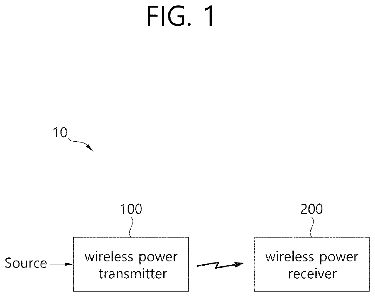
[0052]The term “wireless power”, which will hereinafter be used in this specification, will be used to refer to an arbitrary form of energy that is related to an electric field, a magnetic field, and an electromagnetic field, which is transferred (or transmitted) from a wireless power transmitter to a wireless power receiver without using any physical electromagnetic conductors. The wireless power may also be referred to as a wireless power signal, and this may refer to an oscillating magnetic flux that is enclosed by a primary coil and a secondary coil. For example, power conversion for wirelessly charging devices including mobile phones, cordless phones, iPods, MP3 players, headsets, and so on, within the system will be described in this specification. Generally, the basic principle of the wireless power transfer technique includes, for example, all of a method of transferring power by using magnetic coupling, a method of transferring power by using radio frequency (RF), a method ...


PUM


Abstract

The present disclosure relates to a device and method for controlling transmission of power in a wireless power transmitting system. The present specification discloses a wireless power transmitting method comprising the steps of: performing a digital ping on each of a plurality of coil combinations formed from a plurality of primary coils; receiving a signal intensity packet of each of the coil combinations from the wireless power receiving device; and forming the magnetic coupling by operating a coil combination selected on the basis of the signal intensity packet, and transmitting wireless power to the wireless power receiving device on the basis of the magnetic coupling. Therefore, an optimal multi-coil can be rapidly selected according to the location of the wireless power receiving device.

Description

BACKGROUND OF THE DISCLOSUREField of the Disclosure[0001]The present disclosure relates to wireless charging and, more particularly, to a device and a method for controlling transmission of power in a wireless power transmitting system.Related Art[0002]The wireless power transfer (or transmission) technology corresponds to a technology that can wirelessly transfer (or transmit) power between a power source and an electronic device. For example, by allowing the battery of a wireless device, such as a smartphone or a tablet PC, and so on, to be recharged by simply loading the wireless device on a wireless charging pad, the wireless power transfer technique may provide more outstanding mobility, convenience, and safety as compared to the conventional wired charging environment, which uses a wired charging connector. Apart from the wireless charging of wireless devices, the wireless power transfer technique is raising attention as a replacement for the conventional wired power transfer ...

Claims


Application Information

Patent Timeline
IPC IPC(8): H02J50/40H02J50/12H02J50/80
CPCH02J50/402H02J50/80H02J50/12H04B5/00H02J50/60H02J50/005
Inventor PARK, JOONHOKWAK, BONGSIKKIM, SUNGKYULEE, JIHYUN
Owner LG ELECTRONICS INC
Why Eureka
Eureka Blog
Learn More