Camera system

a camera and system technology, applied in the field of cameras, can solve the problems of high environmental stress, damage to parts or components of cameras, and the inability to meet the high requirements of line of sight, and achieve the effect of high acceleration

Active Publication Date: 2021-01-28
ヘンゾルトオプトロニクスゲーエムベーハー
View PDF0 Cites 5 Cited by
  • Summary
  • Abstract
  • Description
  • Claims
  • Application Information

AI Technical Summary

Benefits of technology

[0005]Proceeding therefrom, the present invention is based on the object of improving a camera system of the type mentioned at the outset, wherein in particular externally introduced high acceleration and / or oscillation loads can act on the camera, without damage occurring to the camera or its components, and without the optical line of sight of the camera being impaired.

Problems solved by technology

When camera systems are used in aircraft, high levels of environmental stress are given due to pressure differences and temperature differences.
High vibration loads or acceleration loads can occur, which have the result that either parts or components of the cameras are damaged or the above-mentioned high requirements with respect to the lines of sight can no longer be met.
It is additionally very unfavorable if the natural resonance frequency of the camera is in the range of the excitation frequency by the air-craft.
This is made more difficult in addition because such cameras have to have a compact structure, since in aviation the installation space available is generally very limited.

Method used


Image

  • Camera system
  • Camera system
  • Camera system

Examples


Embodiment Construction

[0053]Functionally identical elements are provided with the same reference signs in the figures.

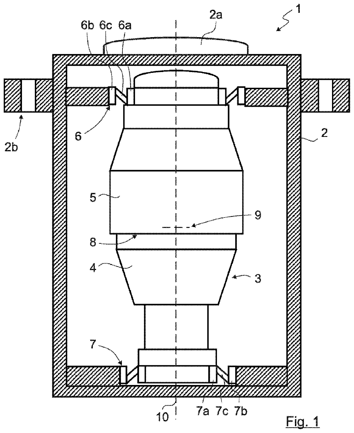
[0054]FIG. 1 shows a camera system 1 according to the invention comprising a housing 2 and an optoelectronic sensor unit 3 arranged in the housing 2 having at least one detector device 4 and at least one optical unit 5 connected upstream of the at least one detector device 4, wherein the optoelectronic sensor unit 3 is elastically suspended or mounted in relation to the housing 2. The housing 2 furthermore has a window 2a and an interface 2b, for example, for installation on a vehicle or aircraft.

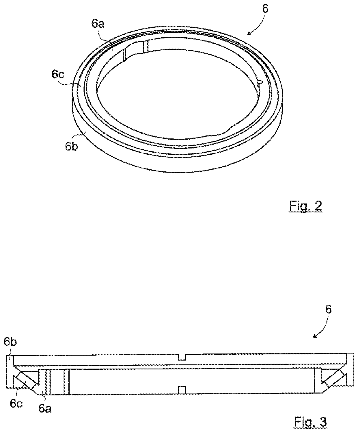
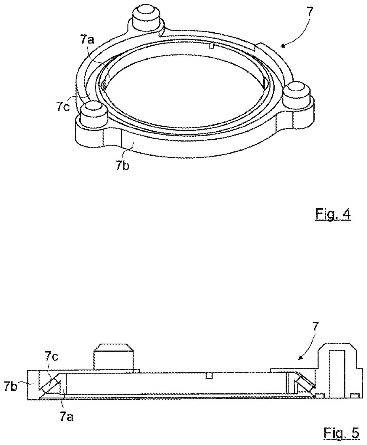
[0055]The optoelectronic sensor unit 3 is connected via at least two elastic mounting devices 6, 7 to the housing 2. In the present exemplary embodiment, the two elastic mounting devices 6, 7 are embodied as ring-shaped or circumferential. In further exemplary embodiments (not shown), however, still other approaches are conceivable.

[0056]As is apparent from FIG. 1, at least one first elastic moun...


PUM

PropertyMeasurementUnit
rigidityaaaaaaaaaa
metallicaaaaaaaaaa
center of gravityaaaaaaaaaa

Abstract

A camera system (1, 1′) which includes a housing (2); and an optoelectronic sensor unit (3), arranged in the housing (2), which has at least one detector device (4) and at least one optical unit (5), connected upstream of the at least one detector device (4). The optoelectronic sensor unit (3) is elastically mounted in relation to the housing (2). At least one elastic mounting device (6.1-6.7) is formed from multiple ring segments (6.10-6.70) arranged spaced apart from one another.

Description

[0001]This application is a national stage completion of PCT / EP2019 / 056044 filed Mar. 11, 2019 which claims priority from German Application No. 10 2018 105 740.7 filed Mar. 13, 2018.FIELD OF THE INVENTION[0002]The invention relates to a camera system comprising a housing and an optronic sensor unit arranged in the housing.BACKGROUND OF THE INVENTION[0003]High demands with respect to the optical lines of sight of the cameras and with respect to the temperature usage range are placed on cameras for aircraft, for example, aircraft having jet engines. When camera systems are used in aircraft, high levels of environmental stress are given due to pressure differences and temperature differences. High vibration loads or acceleration loads can occur, which have the result that either parts or components of the cameras are damaged or the above-mentioned high requirements with respect to the lines of sight can no longer be met. Camera systems mentioned at the outset can be arranged in differ...

Claims


Application Information

Patent Timeline
Patent Type & Authority Applications(United States)
IPC IPC(8): H04N5/225
CPCH04N5/2253B60R11/04H04N5/22521H04N5/2252G03B17/16B64D47/08H04N23/52H04N23/51H04N23/54
Inventor MERZ, SIMONZIEGLER, OLIVER
Owner ヘンゾルトオプトロニクスゲーエムベーハー
Why Eureka
Try Eureka