Filling system for filling a container with a filling product

a technology of filling system and container, which is applied in the direction of synchronising machines, packaging, liquid handling, etc., can solve the problems of contamination of the plant, the inability to guarantee the reliability of the container, and the upper limit of the possible speed of rotation during free jet filling, so as to reduce the tendency of sloshing and increase the performance

Active Publication Date: 2021-02-11
KRONES AG
View PDF0 Cites 0 Cited by
  • Summary
  • Abstract
  • Description
  • Claims
  • Application Information

AI Technical Summary

Benefits of technology

[0008]A filling system which has increased performance and / or a reduced sloshing tendency is described according to various embodiments.

Problems solved by technology

In other words, in a free-jet portion of the free jet process the filling product falls into the container that is to be filled in an unguided manner and without protection.
Thus in conventional rotary filling devices there is an upper limit to the possible speed of rotation during free jet filling.
In this case, not all of the free jet can be conveyed into the interior of the container, and it is not possible to guarantee that the container will be reliably and completely filled with the stream of filling product.
This can also lead to contamination of the plant.
Due to the fact that a deflection device having an electrostatic field is provided, in those areas of the filling system in which excessive deflection of the filling product takes place, for example due to the centrifugal forces which arise, and this deflection leads to sloshing over of the filling product in the container, and / or leads to inaccurate impingement of the stream of filling product on the container during the filling process, it is possible to effect a deflection of the filling product or stream of filling product that counteracts the undesired deflection.

Method used


Image

  • Filling system for filling a container with a filling product
  • Filling system for filling a container with a filling product

Examples


Embodiment Construction

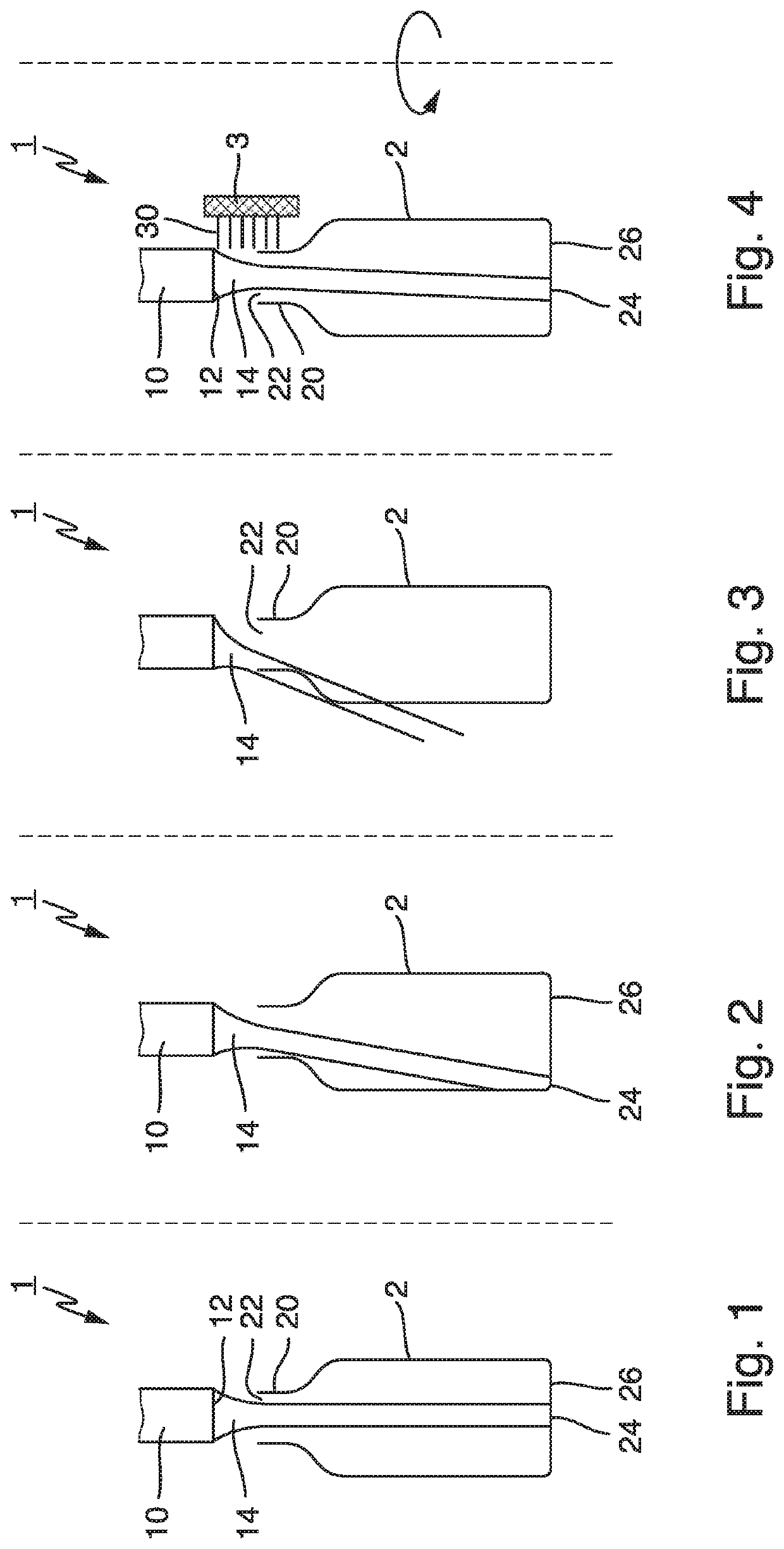
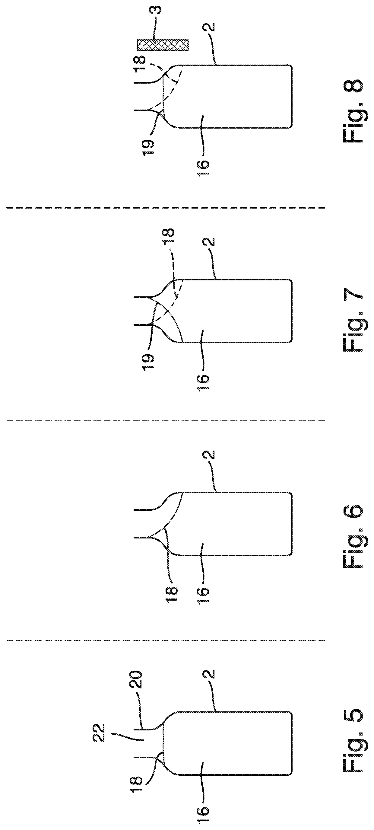
[0036]Examples of embodiments are described below with the aid of the figures. In the figures, elements which are identical or similar, or have identical effects, are designated with identical reference signs. In order to avoid redundancy, repeated description of these elements is in part dispensed with in the description below.

[0037]FIG. 1 shows schematically a section of a filling system 1, wherein the filling system 1 has a rotary-type filling device with a filling element 10, which has a filling product outlet 12. The filling product flows out of the filling element 10, i.e. out of the filling product outlet 12 of the filling element 10, and flows as a stream of filling product 14 into a container 2 that is to be filled, which has a neck area 20 that defines a container mouth 22. The stream of filling product 14 flows through the container mouth 22 of the container 2 that is to be filled into the interior of the container 2 that is to be filled. If the container 2 that is to be ...


PUM


Abstract

A filling system for filling a container with a filling product includes a filling device for filling the container with the filling product, and a deflection device having an electrostatic field for deflecting the filling product relative to the container.

Description

CROSS REFERENCE TO RELATED APPLICATIONS[0001]This application is a national stage of International Application No. PCT / EP2017 / 071281, filed Aug. 24, 2017, which claims priority from German Patent Application No. 10 2016 115 891.7 filed on Aug. 26, 2016 in the German Patent and Trademark Office, the disclosures of which are incorporated herein by reference in their entirety.BACKGROUNDTechnical Field[0002]The present invention relates to a filling system for filling a container with a filling product, for example for filling glass or plastic bottles with beverages.Related Art[0003]Filling systems are known in which the containers that are to be filled are conveyed in transport devices that are designed as rotary machines or carousels. It is for example known in this context to carry out the filling of the containers that are to be filled in a rotary filler, which rotates about its axis during the filling, wherein the filling elements for the actual filling with the filling product of ...

Claims


Application Information

Patent Timeline
Patent Type & Authority Applications(United States)
IPC IPC(8): B67C3/26B67C3/24
CPCB67C3/26B67C2003/2671B67C3/24B67C3/28B67C7/004
Inventor DOBLINGER, JOSEFPOESCHL, STEFANBOCK, TOBIASSTUBENHOFER, MATTHIAS
Owner KRONES AG
Why Eureka
Try Eureka