Edge trimming apparatus

a technology of cutting apparatus and chuck table, which is applied in the direction of grinding machine, edge grinding machine, manufacturing tools, etc., to achieve the effect of preventing the lowering of the suction force of the chuck tabl

Pending Publication Date: 2021-02-11
DISCO CORP
View PDF10 Cites 5 Cited by
  • Summary
  • Abstract
  • Description
  • Claims
  • Application Information

AI Technical Summary

Benefits of technology

[0010]According to the present invention, the wafer can be flatly held by the chuck table that has been cleaned and has an upper surface to which processing dust is not adhered. Therefore, the depth of the recess formed at the circumferential edge of the wafer by edge trimming processing can be made constant. Moreover, because the inside of the ring-shaped groove of the chuck table can be cleaned, it becomes possible to prevent the lowering of the suction force of the chuck table that possibly occurs due to clogging of the ring-shaped groove with processing dust.
[0011]Further, for example, in the edge trimming apparatus including two cutting units opposed to each other, each cutting unit can include the cleaning nozzle as the cleaning unit, and the cleaning areas of the respective cleaning nozzles can be made different to change the role in the cleaning. For example, one cleaning nozzle is used as a nozzle dedicated to intensive cleaning for the region immediately outside the ring-shaped groove in the upper surface of the chuck table and is caused to jet high-pressure water in a circular column shape. Meanwhile, the other cleaning nozzle is used as a nozzle dedicated to cleaning of a ...

Problems solved by technology

However, processing dust enters a gap between the chuck table and the wafer from the circumferential edge of the wafer and the proce...

Method used


Image

  • Edge trimming apparatus
  • Edge trimming apparatus
  • Edge trimming apparatus

Examples


first embodiment

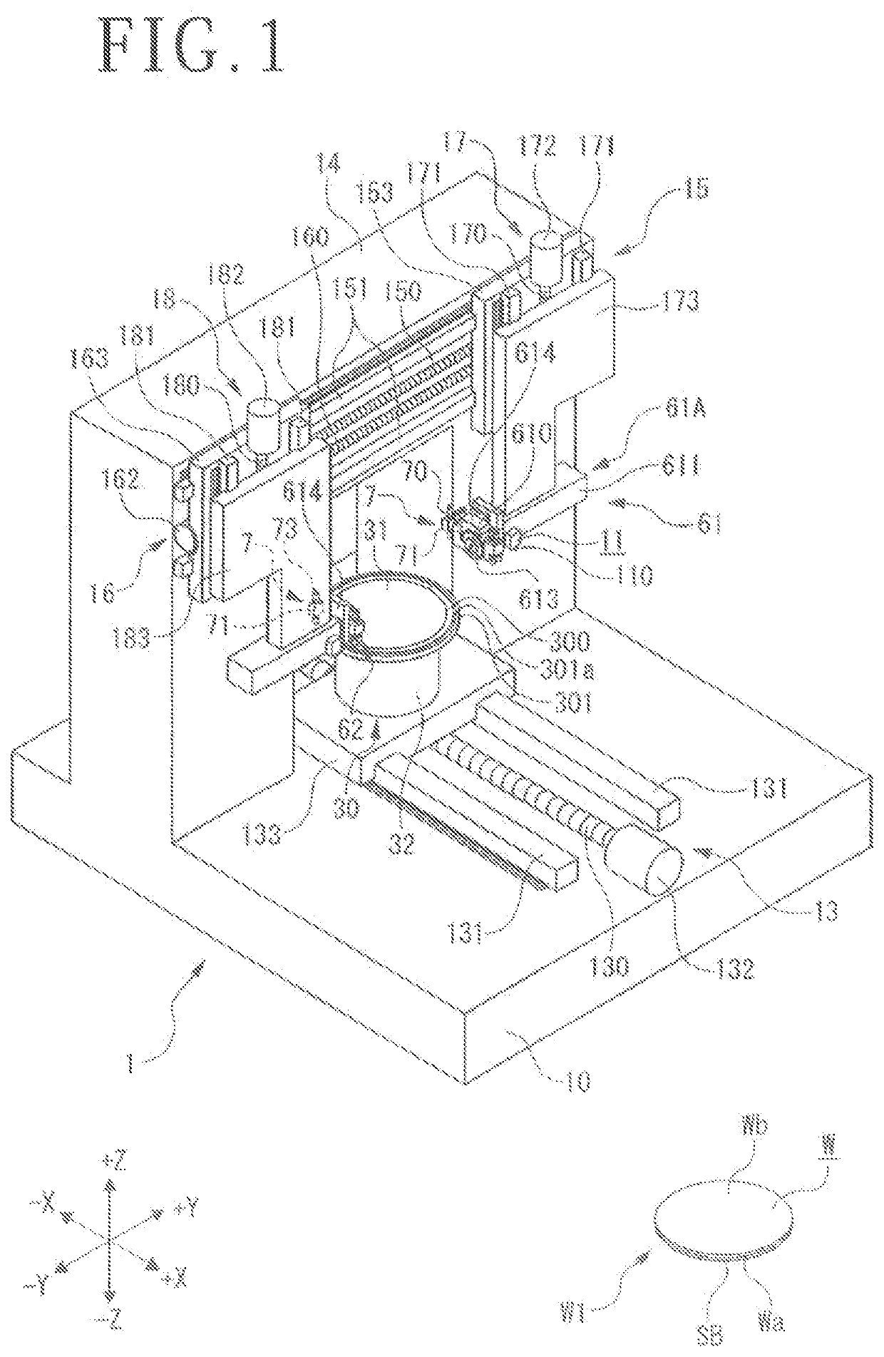
[0023]An edge trimming apparatus 1 illustrated in FIG. 1 according to the present invention (hereinafter, referred to as the edge trimming apparatus 1 of a first embodiment) is an apparatus that can execute edge trimming of a wafer W held by a chuck table 30 by a first cutting unit 61 or a second cutting unit 62 including a cutting blade 613 that rotates. The edge trimming apparatus 1 is not limited to an apparatus of a type that enables dual cutting (two-axis simultaneous cutting) of the wafer W.

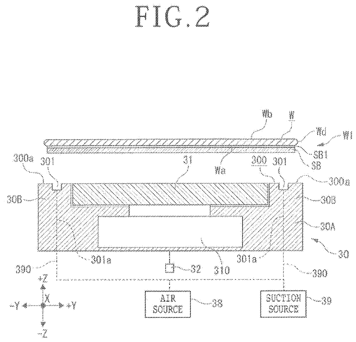
[0024]For example, the wafer W illustrated in FIG. 1 is a semiconductor wafer that includes silicon as the base material and has a circular shape as the outer shape and, on a front surface Wa thereof, unillustrated devices, such as integrated circuits (ICs), are each formed in a respective one of regions marked out in a lattice manner. In the wafer W, chamfering processing has been executed for the circumferential edge, and a chamfered part Wd (see FIG. 2) whose section has a substantially ...

second embodiment

[0071]An edge trimming apparatus 1A of a second embodiment illustrated in FIG. 8 is an apparatus obtained by changing some of constituent elements of the edge trimming apparatus 1 of the first embodiment illustrated in FIG. 1. The part different from the configuration of the edge trimming apparatus 1 of the first embodiment in the edge trimming apparatus 1A of the second embodiment will be described below.

[0072]For example, the edge trimming apparatus 1A includes a cleaning unit 8 of the second embodiment including a sponge 80 illustrated in FIG. 8 and a nozzle 81 for sponge that supplies cleaning water to the sponge 80, in place of the cleaning unit 7 including the cleaning nozzle 70 in the edge trimming apparatus 1 of the first embodiment.

[0073]For example, a support bridge 88 is dispose upright on the base 10 of the edge trimming apparatus 1A in such a manner as to straddle the movement path of the chuck table 30, and the cleaning unit 8 is attached to the support bridge 88. The ...


PUM


Abstract

An edge trimming apparatus includes a chuck table that causes a ring-shaped groove with an outer diameter smaller than the outer diameter of a wafer to communicate with a suction source to hold under suction a lower surface of the wafer by the ring-shaped groove, a cutting unit that rotates a cutting blade and annularly cuts a circumferential part of the wafer held by the chuck table, and a cleaning unit that cleans a region outside the ring-shaped groove in the upper surface of the table and the upper surface of the table including the ring-shaped groove. The cleaning unit is positioned to the region outside the ring-shaped groove in the upper surface of the table and the upper surface of the chuck table including the ring-shaped groove, and the chuck table is rotated to clean the ring-shaped groove and the upper surface.

Description

BACKGROUND OF THE INVENTIONField of the Invention[0001]The present invention relates to an edge trimming apparatus that executes trimming of the circumferential part of a wafer.Description of the Related Art[0002]When a wafer is ground by a grinding abrasive stone and the thickness thereof is made smaller, there is a problem that a chamfered part at the circumference of the wafer becomes a sharp edge and the wafer breaks with the sharp edge being the point of origin. Thus, there is an edge trimming apparatus for removing the circumferential part of a wafer before grinding (for example, refer to Japanese Patent Laid-open No. 2010-165802 or Japanese Patent Laid-open No. 2017-004989).[0003]The edge trimming apparatus brings an abrasive stone into contact with the circumferential part of a wafer held by a holding surface of a chuck table and rotates the wafer to remove the circumferential part. If processing dust discharged due to this edge trimming processing enters a gap between the l...

Claims


Application Information

Patent Timeline
IPC IPC(8): H01L21/67
CPCH01L21/67092H01L21/67046H01L21/67051H01L21/304H01L21/02021H01L21/6838B24B37/30B24B55/045B24B9/065B24B55/04B24B55/06
Inventor MINATO, KOKICHIATENDIDO, PAUL VINCENTKITAURA, TAKESHI
Owner DISCO CORP
Why Eureka
Try Eureka