
Terminal of supporting leakage detection, and method for performing leakage detection for the terminal

a technology of supporting and leakage detection, applied in the direction of short-circuit testing, instruments, measurement devices, etc., can solve the problems of metal terminals and user injuries touching external metals

Active Publication Date: 2021-02-18
SAMSUNG ELECTRONICS CO LTD
View PDF0 Cites 1 Cited by
  • Summary
  • Abstract
  • Description
  • Claims
  • Application Information

AI Technical Summary

Benefits of technology

The patent text describes a technology that improves the efficiency of solar cells. This technology involves using a special coating on the surface of the solar cells that reduces reflection of sunlight and increases the amount of sunlight that can be captured and converted into electrical energy. This results in more efficient and effective solar cells.

Problems solved by technology

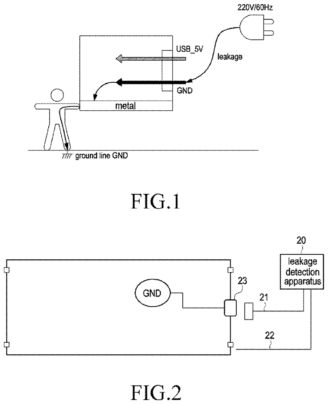
For example, as shown in FIG. 1, if a charger connected to an external interface or an associated connection line leaks, a leakage current can flow into the metal terminal through the external interface, and at this time, if there is also leakage between a ground line GND inside the metal terminal and a external metal of a external edge of the metal terminal, the leakage current flowing into the metal terminal will cause injury to a user touching the external metal.
However, in reality, in order to ensure a beautiful appearance of the metal terminal with metal materials, the external metal of the metal terminal is often subjected to color covering and spraying, for example, painting or anodizing or the like, which causes the external metal to be in an insulated state, thereby causing that there is no exposed test point for leakage test outside the metal terminal.

Method used


Image

  • Terminal of supporting leakage detection, and method for performing leakage detection for the terminal
  • Terminal of supporting leakage detection, and method for performing leakage detection for the terminal
  • Terminal of supporting leakage detection, and method for performing leakage detection for the terminal

Examples


Embodiment Construction

[0036]Exemplary embodiments of the present invention will be described in detail below with reference to the drawings in which the same reference numerals always refer to the same part.

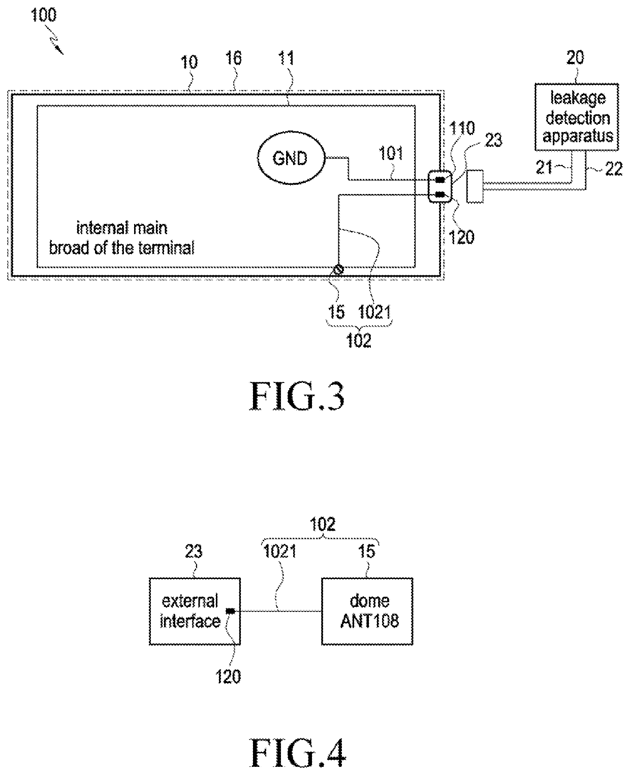
[0037]FIG. 3 is a diagram illustrating a configuration of a terminal 100 supporting leakage detection according to an exemplary embodiment of the present invention.

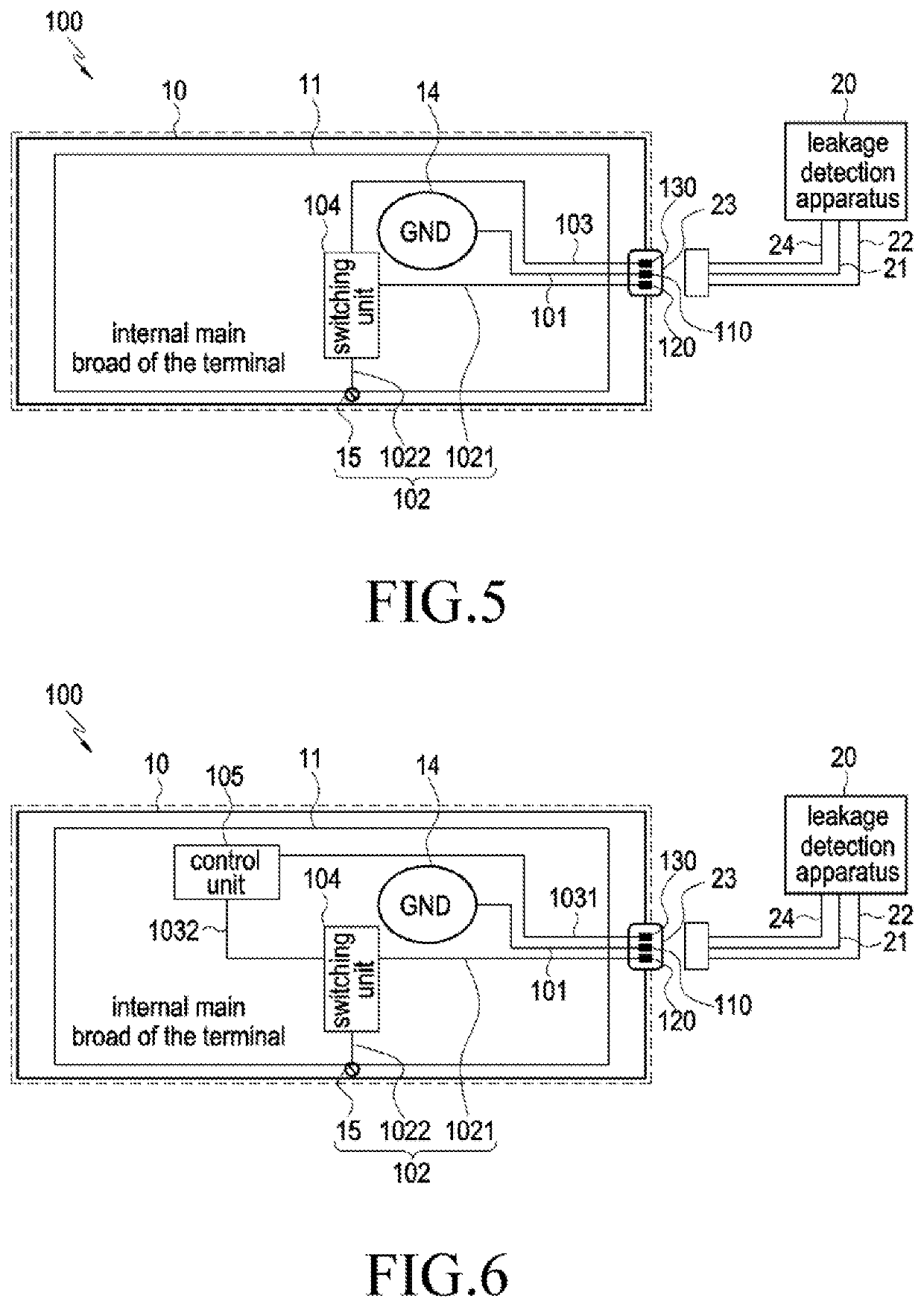
[0038]As shown in FIG. 3, a metal portion 10 (i.e., a external metal) of a outer casing of the terminal 100 whose appearance is covered and sprayed (i.e., a insulating layer 16 is formed, as shown by a outer dotted line of the terminal 100) is a continuous whole, i.e., the outer casing of the terminal 100 has a continuous metal portion 10. The terminal 100 may include a first conductive unit 101, a second conductive unit 102, a first access end 110, and a second access end 120, wherein the first access end 110 may be configured to be connected to a ground line GND of a main board 11 of the terminal 100 through the first conductive unit 101,...


PUM


Abstract

A terminal supporting leakage detection and a detection method for performing leakage detection for the terminal is provided, the terminal may include: a first conductive unit, a second conductive unit, a first access end, and a second access end, wherein the first access end is configured to be connected to a ground line of a main board of the terminal through the first conductive unit and used to access a ground line of an external leakage detection apparatus, and the second access end is configured to be connected inside the terminal to a metal portion of a outer casing of the terminal through the second conductive unit and used to access a leakage test line of the leakage detection apparatus.

Description

TECHNICAL FIELD[0001]The present application relates to a leakage detection technology for a terminal, and more particularly to a terminal that supports leakage detection after the terminal is assembled and a detection method for performing leakage detection for the terminal.BACKGROUND ART[0002]In the art, there may be leakage between an external metal and an internal main board of the metal terminal after a metal terminal completes a finished product assembly, and in this case, if a user connects non-standard power lines, chargers or serial ports to the metal terminal, since there may also be leakages in these non-standard power line, charger or serial ports themselves, a leakage current of these non-standard power lines, chargers or serial ports may be transmitted to an external metal area of the metal terminal through a leakage path between the internal main board of the metal terminal and the external metal of the metal terminal, and if the user touches an area of the external m...

Claims


Application Information

Patent Timeline
Patent Type & Authority Applications(United States)
IPC IPC(8): G01R31/52G01R31/56
CPCG01R31/52G01R31/56
Inventor ZHENG, JICHENGYANG, JIAYILI, JINTAOJIN, SONGMINZOU, WENJIE
Owner SAMSUNG ELECTRONICS CO LTD
Learn More