
Cannula with illumination

a cannula and illumination technology, applied in the field of minimally invasive surgery, can solve the problems of death and disabling neurologic disorders, and achieve the effects of reducing the overall beam angle, minimizing glare, and improving visualization of diseased tissu

Active Publication Date: 2021-02-25
REBOUND THERAPEUTICS CORP
View PDF3 Cites 1 Cited by
  • Summary
  • Abstract
  • Description
  • Claims
  • Application Information

AI Technical Summary

Benefits of technology

The patent describes a cannula system with a camera attached to the end that can be used to better visualize diseased tissue in the body. The system uses powerful LEDs and additional lenses to focus the light from the camera to a narrow beam angle, reducing glare. The goal is to provide a clear view of the surgical workspace at the end of the cannula. The overall effect is improved visualization for better surgical procedures.

Problems solved by technology

Stroke is a common cause of death and disabling neurologic disorder.

Method used


Image

  • Cannula with illumination
  • Cannula with illumination
  • Cannula with illumination

Examples


Embodiment Construction

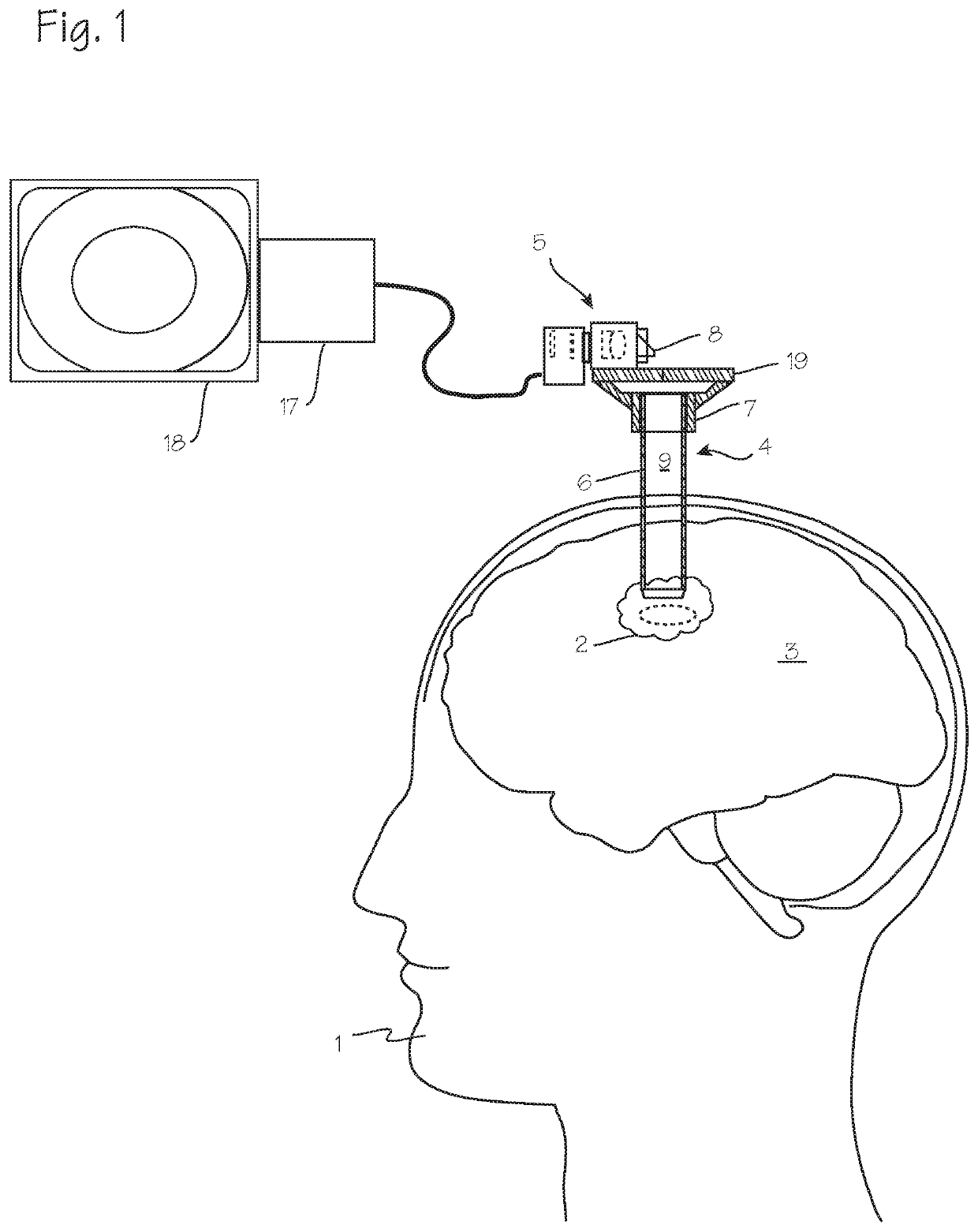
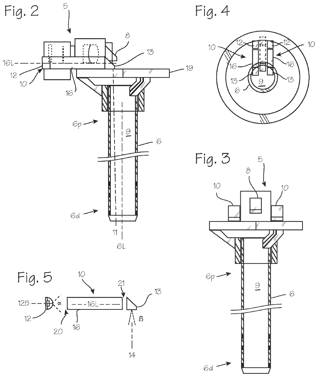
[0009]FIGS. 1, 2 and 3 illustrate a cannula system that may be conveniently used in a minimally invasive surgery. FIG. 1 illustrates a patient 1 with diseased tissue 2 in the brain 3 that necessitates surgical intervention, with a cannula 4 which has been inserted into diseased tissue, with the distal end of the cannula proximate the diseased tissue. The diseased tissue may be a glioma or glioblastoma in the brain, an ependymoma in the spine, or other diseased tissue.

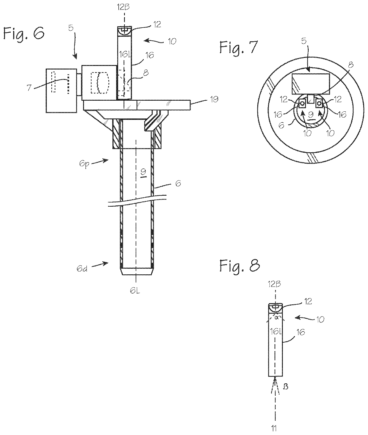
[0010]A camera 5 is mounted on the proximal rim of the cannula, with a portion of the camera overhanging the rim of the cannula and disposed over the lumen of the cannula, and is operable to obtain video or still images of the distal end of the cannula lumen, including target tissue at the distal end of the cannula such as the brain and any diseased tissue in the brain. As shown in both FIGS. 1 and 2 and 3, the cannula comprises a cannula tube 6 with a distal end 6d adapted for insertion into the body of the patient. Th...


PUM


Abstract

A cannula with a proximally mounted camera and proximally mounted light sources. The lighting sources have beam axes directed distally, toward a workspace at the distal end of the cannula. The light sources are coupled with focusing lenses, to reduce the beam angle of the lighting sources and reduce glare within the cannula tube.

Description

FIELD OF THE INVENTIONS[0001]The inventions described below relate to the field of minimally invasive surgery for the treatment of tumors.BACKGROUND OF THE INVENTIONS[0002]Stroke is a common cause of death and disabling neurologic disorder. Approximately 700,000 patients suffer from stroke in the United States every year. Hemorrhagic stroke accounts for 20% of the annual stroke population. Hemorrhagic stroke is due to a rupture of a blood vessel in the brain, causing bleeding into the brain tissue and resulting in a hematoma (a blood mass) in the brain. Prompt removal of the blood mass is necessary to limit or prevent long-term brain injury.[0003]Clear visualization and imaging of the blood mass and any surrounding surgical field facilitates removal of the blood mass. In U.S. Pat. No. 10,172,525, we disclose cannula with a camera mounted on the proximal end of the cannula with a view into the cannula lumen and the tissue within and below the lumen. In that system, illumination was p...

Claims


Application Information

Patent Timeline
Patent Type & Authority Applications(United States)
IPC IPC(8): A61B17/34A61B1/04A61B1/313A61B1/00A61B1/06A61B90/30A61B5/00
CPCA61B17/3423A61B1/042A61B1/313A61B5/0042A61B1/0669A61B90/30A61B1/00096A61B2090/309A61B90/361A61B2090/3618A61B17/3421A61B90/10G03B15/05G03B15/14G03B2215/0567A61B5/0084A61B5/6848A61B5/4064A61B2576/026A61B5/02042H04N23/555H04N23/56H04N23/57A61B90/13
Inventor TSUKASHIMA, ROSSFULLER, DONALD JOSEPHSCHMIDT, JACK H.
Owner REBOUND THERAPEUTICS CORP
Learn More