Electric vehicle charging station

a charging station and electric vehicle technology, applied in charging stations, electric vehicle charging technology, transportation and packaging, etc., can solve the problems of increasing congestion among pedestrians, increasing street cleaning difficulty, and affecting street cleanliness, so as to reduce the requirements of below-ground space and mitigate electrical hazards

Active Publication Date: 2021-02-25
URBAN ELECTRIC NETWORKS LTD
View PDF0 Cites 16 Cited by
  • Summary
  • Abstract
  • Description
  • Claims
  • Application Information

AI Technical Summary

Benefits of technology

[0049]The station may be adapted to detect if it is impacted. The station may be adapted to stop or prevent pillar movement if impacted. The station or pillar may be adapted to cease charging and / or isolate the mains power supply and / or ground the station, if an impact occurs. For example, a tilt sensor or accelerometer may be provided to detect an impact. The controller may then immobilise the pillar and / or isolate and ground the station to mitigate the electrical hazard, should there be sufficient damage to expose electrically charged portions.
[0050]The pillar may include a third section, the third section being a tubular member having a side wall defining a hollow interior and two ends, and the third section being slidably disposed within the hollow interior of the second section. This allows the pillar to collapse to a smaller length while being able to support the socket at the same height, reducing the below-ground space requirements.

Problems solved by technology

However, in areas with high pedestrian footfall this can be undesirable as it restricts pavement space, increasing congestion among pedestrians.
Charging station columns may also be considered unsightly as they lead to a more cluttered urban environment.
Finally, the presence of additional fixed street furniture makes street cleaning more difficult, as it necessitates cleaning around the street furniture.
In addition to the lack of above-ground space in busy urban environments, there is often limited availability of space below ground.
The depth of excavations is typically limited to avoid disturbing utilities such as water pipes, power cables and drainage, which may be installed relatively close to the surface in some areas.

Method used


Image

  • Electric vehicle charging station
  • Electric vehicle charging station
  • Electric vehicle charging station

Examples


Embodiment Construction

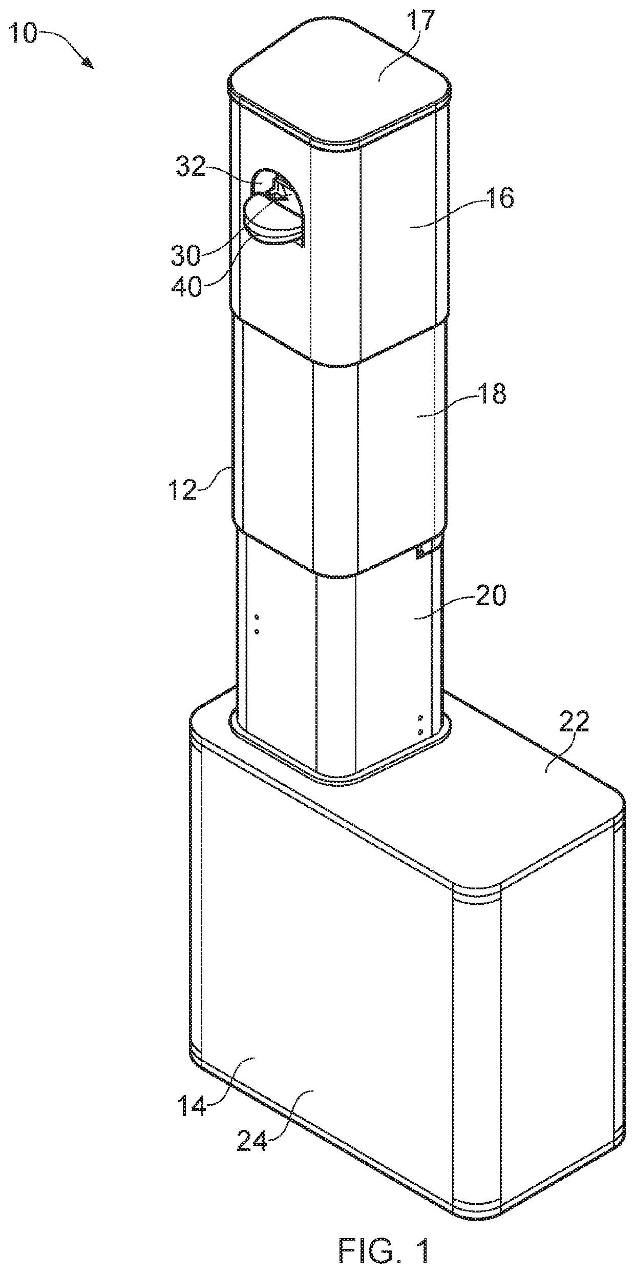
[0122]Referring firstly to FIG. 1, an electric vehicle charging station is indicated generally at 10.

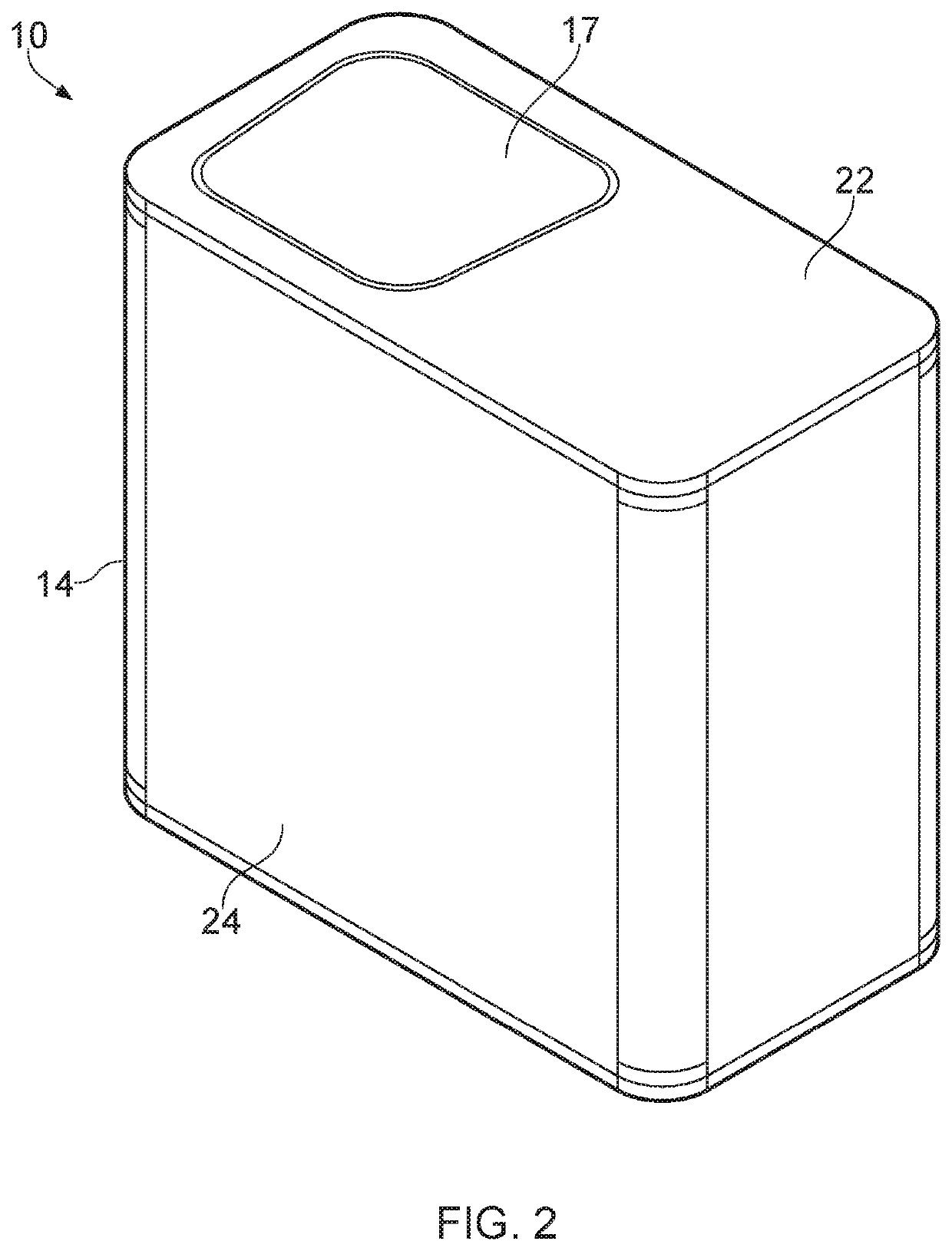
[0123]The electric vehicle charging station 10 includes a pillar 12 and a casing 14.

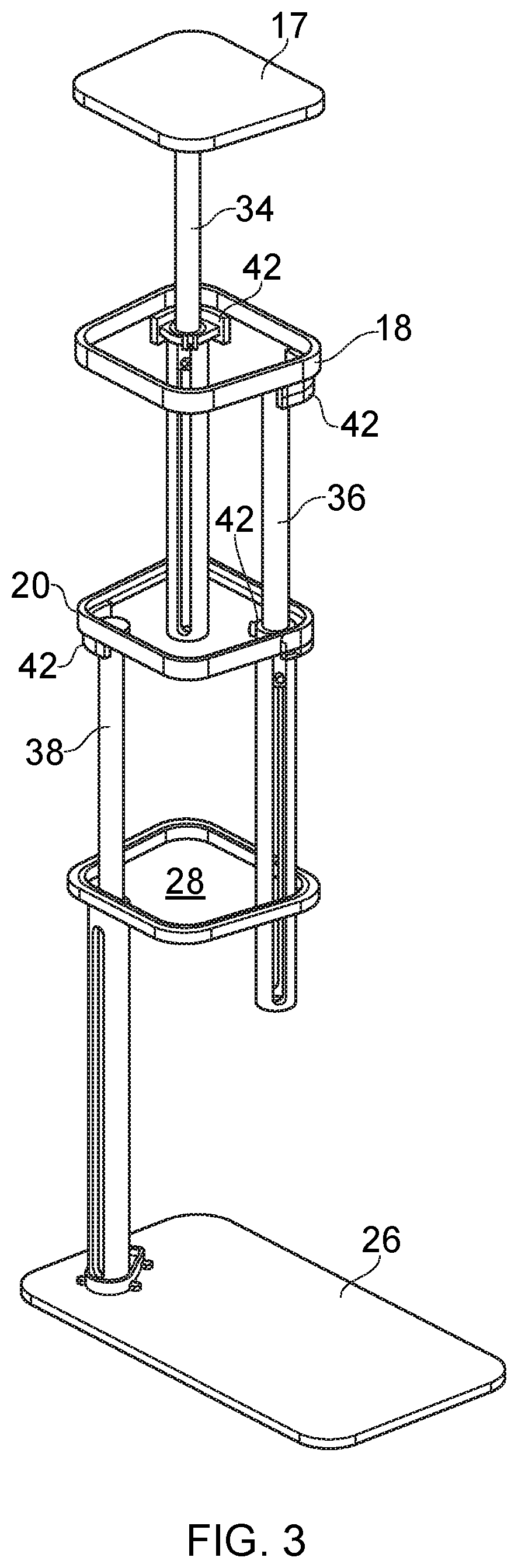
[0124]The pillar 12 includes three sections 16, 18, 20. The pillar 12 includes a top section 16, a middle section 18 and a bottom section 20.

[0125]Each section 16, 18, 20 is a tubular member having a side wall defining a hollow interior and two ends. Each section 16, 18, 20 has a top end and a bottom end. Each section is a prism, i.e. a profile that has been extruded along an axis. The profile of each side wall has the form of a trapezium with rounded corners.

[0126]The profile of the top section 16 is the largest. The profile of the middle section 18 is slightly smaller than the profile of the top section 16 and fits tightly within the top section 16. The profile of the bottom section 20 is slightly smaller than the profile of the middle section 18 and fits tightly within the middle section 18. The th...


PUM


Abstract

An electric vehicle charging station (10) comprises a pillar (12) and a casing (14) for installing underground. The casing (14) has a base (26), a side wall (24) and a top (22) defining an inner space, an opening (28) being provided in the top (22) for receiving the pillar (12). The electric vehicle charging station (10) includes a power socket (30) for connection to a power supply and for receiving a power connector of an electric vehicle. The power socket (30) is joined to the pillar (12) and situated near a top end of the pillar (12), the bottom end of the pillar (12) is received in the opening (28) of the casing and the pillar (12) is movable between a retracted position for storing the pillar (12) within the inner space of the casing (14) below ground, and an extended position for supporting the power socket (30) outside the casing (14) above ground.

Description

[0001]The present invention relates to an electric vehicle charging station.BACKGROUND TO THE INVENTION[0002]Electric vehicles are increasingly popular, particularly electric cars. Electric vehicle batteries must be recharged regularly, and this requires the vehicle to be parked next to a charging station for an extended period of time, typically over 40 minutes. Because of the non-instantaneous nature of charging, as opposed to refuelling a petrol or diesel vehicle, there is a need to provide a large number of charging stations to service the needs of the growing numbers of electric cars in use.[0003]Because of this, many cities have installed electric vehicle charging stations on streets. Typically, the electric vehicle charging station includes a column installed on the pavement on which is mounted one or more sockets connected to mains power. The sockets must be mounted on a column or other structure to support the charging socket at an appropriate height, and this is a regulato...

Claims


Application Information

Patent Timeline
Patent Type & Authority Applications(United States)
IPC IPC(8): B60L53/31B60L53/16B60L53/18B60L53/35
CPCB60L53/31B60L53/35B60L53/18B60L53/16B60L53/14Y02T10/70Y02T90/12Y02T10/7072Y02T90/14B60L53/30
Inventor FREELING-WILKINSON, OLIVIER
Owner URBAN ELECTRIC NETWORKS LTD
Why Eureka
Try Eureka