
Method and device for setting a dead time of switching elements of a half bridge, and inverter

a switching element and dead time technology, applied in electronic switching, pulse technique, power conversion systems, etc., can solve the problems of unsatisfactory heating of half bridge power semiconductors, and achieve the effects of reducing dead time, strong heating of switching elements, and good efficiency

Active Publication Date: 2021-02-25
ROBERT BOSCH GMBH
View PDF2 Cites 1 Cited by
  • Summary
  • Abstract
  • Description
  • Claims
  • Application Information

AI Technical Summary

Benefits of technology

The patent text describes a method to improve the efficiency of an inverter used for supplying power to a drive machine, such as a motor vehicle. The method involves measuring the temperature of the switching elements in real-time to detect any potential for thermal effects, such as short circuits, caused by the reduced dead time. By adjusting the value of the dead time, the method ensures that the inverter operates at maximum efficiency without causing excessive heating. The method can be performed during the initial start-up of the inverter or during normal operation. Overall, the method allows for a reduction in the time required to reach a steady state of operation and ensures a steady output of power from the inverter.

Problems solved by technology

As a result of the delayed development of electromagnetic fields of the half bridge power semiconductors, cross-influences would otherwise arise that could lead to an undesirable heating of the half bridge power semiconductors.

Method used


Image

  • Method and device for setting a dead time of switching elements of a half bridge, and inverter
  • Method and device for setting a dead time of switching elements of a half bridge, and inverter
  • Method and device for setting a dead time of switching elements of a half bridge, and inverter

Examples


Embodiment Construction

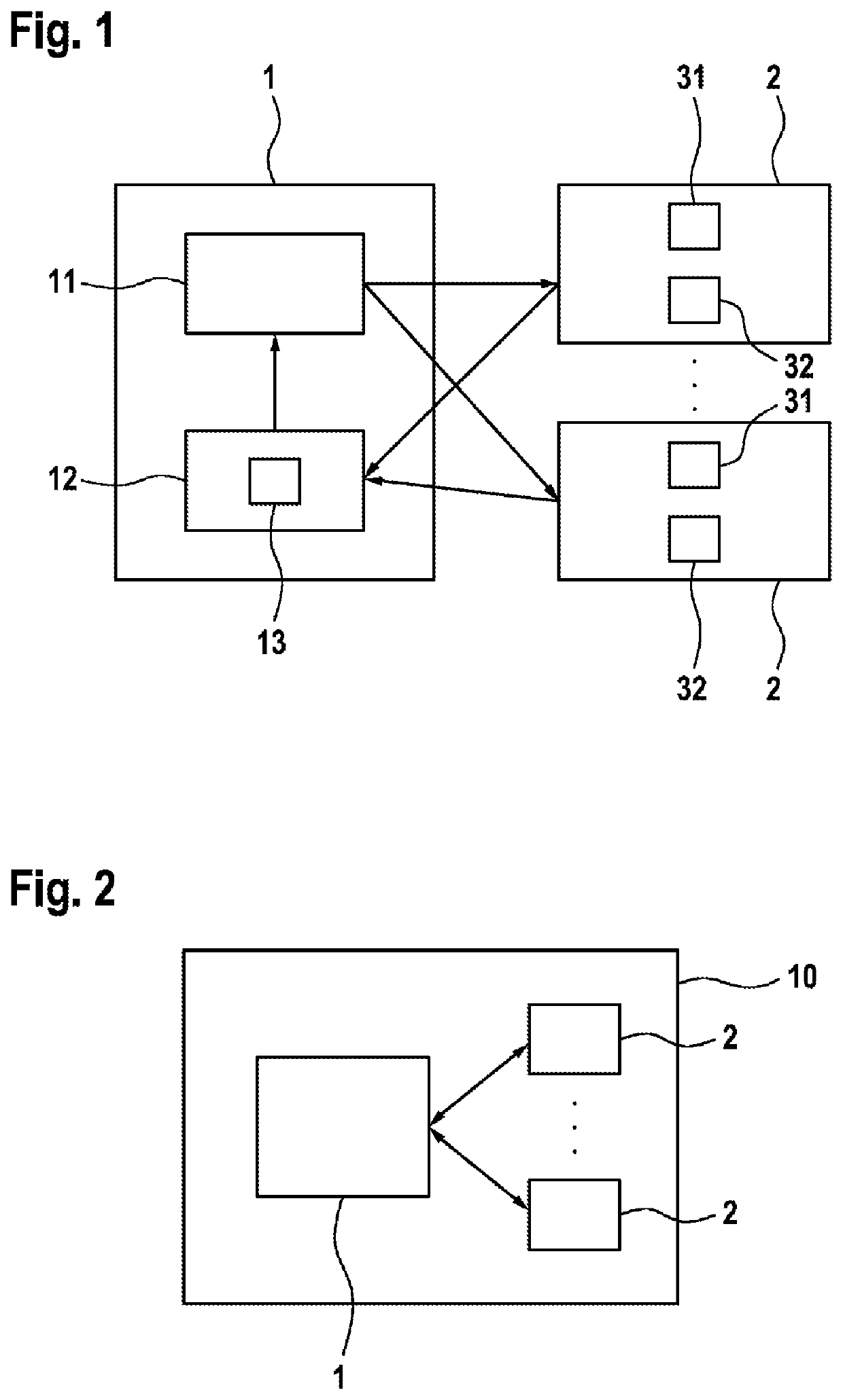
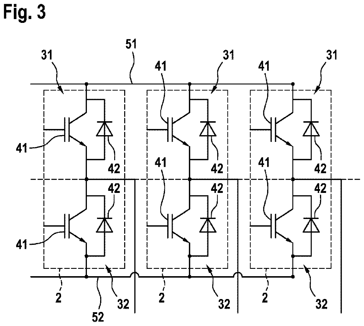
[0033]FIG. 1 shows a schematic block diagram of a device 1 for setting a dead time tTD between the opening of a respective first switching element 31 and the closing of a respective second switching element 32 of half bridges 2. The half bridges 2 can be part of an inverter which in turn can be an element of an electric drive system. The inverter is connected for this purpose to a DC voltage source, and converts the DC voltage provided at the input side into an alternating voltage that is provided at the output side to a multiphase electric machine. For each phase of the electric machine, the inverter comprises a corresponding half bridge 2. A three-phase electric machine, for example, can be driven by means of a B6 bridge consisting of three half bridges 2.

[0034]The switching elements 31, 32 are arranged in series between a positive input terminal of the inverter and a negative input terminal of the inverter. A connecting point between the first and second switching elements of the...


PUM


Abstract

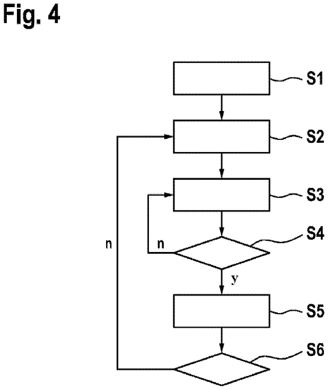
The invention relates to a method for setting a dead time between the opening of a first switching element (31) of a half bridge (2) and the closing of a second switching element (32) of the half bridge (2), comprising the steps: reducing the dead time of a switching cycle relative to the dead time of a preceding switching cycle, and determining a temperature of at least one of the switching elements (31, 32); wherein the steps of reducing the dead time and of determining the temperature are repeated for subsequent switching cycles until a critical dead time is reached, in the case of which a termination condition, which depends on the determined temperature, is fulfilled; and wherein the dead time is set using the critical dead time.

Description

BACKGROUND OF THE INVENTION[0001]The present invention relates to a method and a device for setting a dead time between the opening of a first switching element of a half bridge and the closing of a second switching element of the half bridge. The invention further relates to an inverter and, preferably, an inverter for an electric machine.[0002]Electric machines of drive systems can be supplied with alternating voltage via an inverter. An exemplary drive of an inverter is known from document DE 10 2011 081 173 A1. The inverter comprises a plurality of half bridges, wherein the number of half bridges corresponds to the number of phases of the electric machine. The half bridges each comprise two switching elements connected in series, wherein, in order to prevent a short circuit, the switching elements must not be closed at the same time. It is in addition necessary to ensure that in the course of the commutation, the second switching element is also not closed immediately after the ...

Claims


Application Information

Patent Timeline
Patent Type & Authority Applications(United States)
IPC IPC(8): H02M1/32H02M7/5387H02P27/06H02P29/024H02M1/38H03K17/16
CPCH02M1/32H02M7/5387H03K17/165H02P29/0241H02M1/38H02P27/06H03K17/08128H03K2017/0806
Inventor GEYER, HANS
Owner ROBERT BOSCH GMBH
Learn More