Conveyance roller for heating furnace

a technology of conveying roller and heating furnace, which is applied in the direction of furnaces, heat treatment apparatus, charge manipulation, etc., can solve the problems of preventing the movement and affecting the cooling effect of the conveying roller. , to achieve the effect of suppressing local deformation, suppressing the deformation of the outer circumferential surface, and suppressing the rapid cooling of the conveying roller

Inactive Publication Date: 2021-03-04
NORITAKE CO LTD
View PDF1 Cites 0 Cited by
  • Summary
  • Abstract
  • Description
  • Claims
  • Application Information

AI Technical Summary

Benefits of technology

[0016]According to the conveyance roller for the heating furnace of the first aspect of the invention, the object to be heated is held or conveyed while being held by the holding protrusion made of the heat-resistant alloy and provided on the outer circumferential surface of the roller body, wherein the holding protrusion protrudes from the outer circumferential surface of the roller body in the plurality of positions at the given interval in the longitudinal direction of the roller body, and has a height larger than the shielding member. In this instance, the holding protrusion made of the heat-resistant alloy is in contact at a small contact area with the cold object so that heat transmission from the roller body having a high temperature to the object is small, and heat radiation from the roller body having the high temperature is shielded by the shielding member provided between the holding protrusion so that rapid cooling of the roller body is suppressed, whereby local deformations of the outer circumferential surface of the roller body are suppressed. Thus, since the local deformations of the outer circumferential surface of the roller body are suppressed, the holding protrusion is not deformed and obstacle to the conveyance of the object is cleared. Particularly, where the conveyance roller is used in an intermittent conveyance in which the conveyance roller having the high temperature holds a cold steel sheet with its rotation being stopped for a rotation stop time, the cold steel sheet is avoided from being brought into direct contact with the outer circumferential surface of the roller body, and the radiative cooling from the roller body having the high temperature is suppressed by the shielding member that is interposed between the cold steel sheet and the roller body, so that it is possible to advantageously suppress the local deformations of the outer circumferential surface of the roller body which are successions of bulges in its circumferential direction.
[0017]According to the conveyance roller for the heating furnace of the second aspect of the invention, the holding protrusion is constituted by the plurality of annular-shaped wires or annular-shaped built-up welded members which are made of the heat-resistant alloy and which are welded on the outer circumferential surface of the roller body in the plurality of positions at the given interval in the longitudinal direction of the roller body. Owing to this arrangement, the object to be heated is held by the roller body exclusively through the plurality of annular-shaped wires or annular-shaped built-up welded members, whereby the cold object is avoided from being brought into direct contact with the outer circumferential surface of the roller body, so that it is possible to suppress the deformations of the outer circumferential surface of the roller body.
[0018]According to the conveyance roller for the heating furnace of the third aspect of the invention, the holding protrusion is constituted by the single helical-shaped wire or single helical-shaped built-up welded member which is made of the heat-resistant alloy and which is helically welded on the outer circumferential surface of the roller body. Owing to this arrangement, the object to be heated is held by the roller body exclusively through the single helical-shaped wire or single helical-shaped built-up welded member, whereby the cold object is avoided from being brought into direct contact with the outer circumferential surface of the roller body, so that it is possible to suppress the deformations of the outer circumferential surface of the roller body. Further, since the helical-shaped wire or helical-shaped built-up welded member is constituted by a single heat-resistant metallic wire that is continuously welded on the outer circumferential surface of the roller body, the conveyance roller can be manufactured easier as compared with an arrangement in which the plurality of annular-shaped wires are constituted.
[0019]According to the conveyance roller for the heating furnace of the fourth aspect of the invention, the shielding member is constituted by one or two or more short tubes made of the heat-resistant alloy and having the thickness not larger than the height of the holding protrusion from the outer circumferential surface of the roller body, such that the short tubes are provided between the holding protrusion and is fitted on the outer circumferential surface of the roller body with a given amount of play. In this arrangement, the short tube can be easily formed by cutting a tube having certain dimensions, i.e., a thickness that is not larger than the height of the holding protrusion from the outer circumferential surface of the roller body and an inside diameter that is larger than an outside diameter of the roller body.
[0020]According to the conveyance roller for the heating furnace of the fifth aspect of the invention, the shielding member is constituted by the heat-insulating material member having the thickness not larger than the height of the holding protrusion from the outer circumferential surface of the roller body, such that the heat-insulating material member is wound between the holding protrusion and covers the outer circumferential surface of the roller body. In this arrangement, the shielding member can be easily formed by winding a strip-shaped heat-insulating material member woven from a fiber of heat-insulating material such as a ceramic fiber like fused silica and alumina, by at least one round, and sewing ends of the strip-shaped heat-insulating material member together.
[0021]According to the conveyance roller for the heating furnace of the sixth aspect of the invention, the shielding member is formed to a helical tubular shape from the heat-insulating material member having the thickness not larger than the height of the holding protrusion from the outer circumferential surface of the roller body, such that the heat-insulating material member is wound between the helical-shaped wire or the helical-shaped built-up welded member and covers the outer circumferential surface of the roller body. In this arrangement, the shielding member can be further easily formed by winding a strip-shaped heat-insulating material member woven from a fiber of heat-insulating material such as a ceramic fiber like fused silica and alumina, between the helical-shaped wire or the helical-shaped built-up welded member, by at least one round and fixing ends of the strip-shaped heat-insulating material member together.

Problems solved by technology

The conveyance roller used in such a heating furnace, when being used for a relatively long time, is likely to suffer from local deformations of its outer circumferential surface which are successions of bulges in its circumferential direction, which could be an obstacle to conveyance of the object to be heated.
For example, there is a problem that a direction of the conveyance of the object is deviated whereby the object is conveyed to a variable position or the object interferes with a wall of the heating furnace thereby causing conveyance stuck.
This problem is caused also where the inner tubular member is not provided in the conveyance roller.

Method used


Image

  • Conveyance roller for heating furnace
  • Conveyance roller for heating furnace
  • Conveyance roller for heating furnace

Examples


embodiment 1

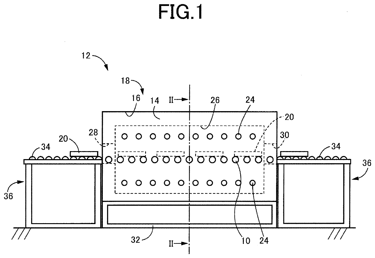
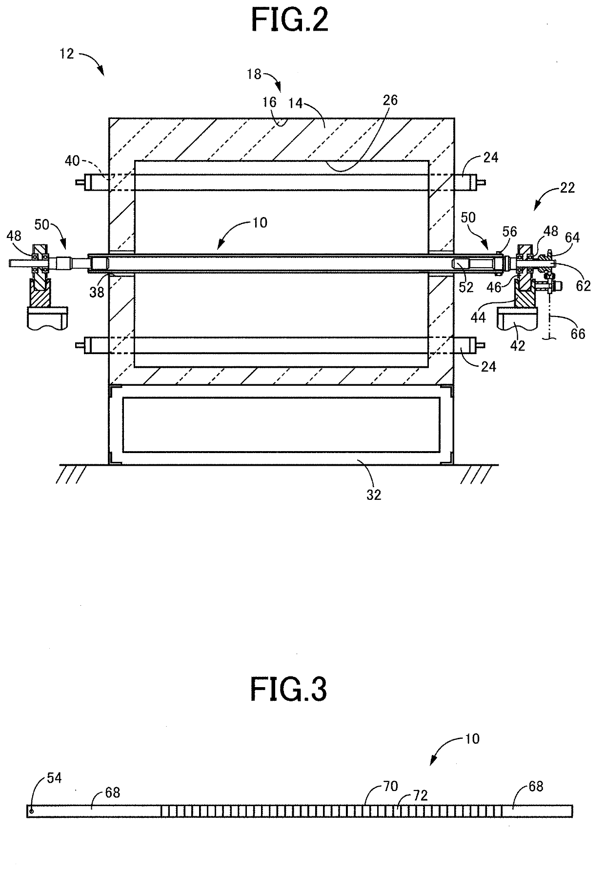
[0036]FIG. 1 is a side view of an intermittent-conveyance type steel-sheet heating furnace 12 as an example of a heating furnace provided with a heating-furnace conveyance rollers (hereinafter referred to as conveyance rollers) 10, which is an embodiment of the present invention. FIG. 2 is a cross sectional view of the intermittent-conveyance type steel-sheet heating furnace 12 of FIG. 1, taken along line II-II in FIG. 1. The intermittent-conveyance type steel-sheet heating furnace 12 includes: an elongated-shaped furnace body 18 consisting of a heat-insulating material member 14 configured to keep a high temperature state inside the heating furnace and a casing 16 covering the heat-insulating material member 14; the plurality of conveyance rollers 10 arranged to be parallel to each other at a given interval so as to hold and convey a steel sheet 20 as an object to be heated, in a direction away from one of opposite end portions of the furnace body 18 in a longitudinal direction of ...

embodiment 2

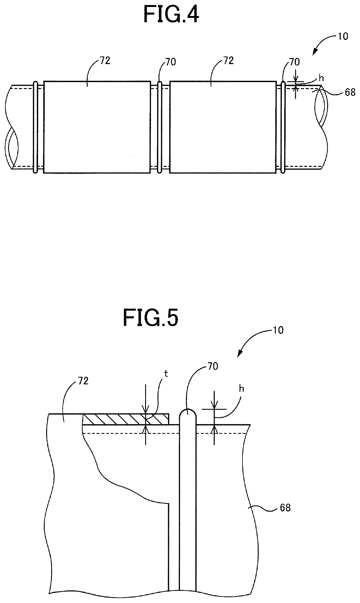
[0055]FIG. 9 is a view corresponding to FIG. 5 and showing a conveyance roller 110 according to another embodiment of the present invention. In the embodiment shown in FIG. 5, the shielding member 72 is constituted by the short tube made of the heat-resistant alloy. However, like a shielding member 172 shown in FIG. 9, the shielding member may be constituted by, in place of the short tube made of the heat-resistant alloy, a heat-insulating material member which has a thickness not larger than the height h of the holding protrusions 70 from the outer circumferential surface of the roller body 68 and which is provided between the holding protrusions 70 so as to be wounded on the outer circumferential surface of the roller body 68, so that the outer circumferential surface of the roller body 68 is covered by the heat-insulating material member. This heat-insulating material member is constituted by, for example, a strip-shaped heat-insulating material member woven from a fiber of heat-...

embodiment 3

[0057]FIG. 10 is a view corresponding to FIG. 4 and showing a major portion of a conveyance roller 210 according to another embodiment of the present invention. In FIG. 10, a holding protrusion 270 is constituted by a single helical-shaped wire made of a heat-resistant alloy and helically welded on the outer circumferential surface of the roller body 68. Further, a shielding member 272, which is constituted by a heat-insulating material member having a thickness not larger than a height h of the holding protrusion 270 from the outer circumferential surface of the roller body 68, is disposed between the helical-shaped wire in the longitudinal direction of the roller body 68, so as to cover the outer circumferential surface of the roller body 68. This shielding member 272 can be easily formed by winding a strip-shaped heat-insulating material member woven from a fiber of heat-insulating material such as a ceramic fiber like fused silica and alumina, by at least one round, and sewing e...


PUM

PropertyMeasurementUnit
temperatureaaaaaaaaaa
diameteraaaaaaaaaa
lengthaaaaaaaaaa

Abstract

A conveyance roller for a heating furnace includes: a roller body constituted by a metal tube made of a heat-resistant alloy; at least one holding protrusion provided on an outer circumferential surface of the roller body for holding an object to be heated in the heating furnace, and protruding from the outer circumferential surface of the roller body in a plurality of positions at a given interval in a longitudinal direction of the roller body; and at least one shielding member provided to be adjacent to the at least one the holding protrusion in the longitudinal direction, and covering the outer circumferential surface of the roller body. The at least one shielding member has a thickness not larger than a height of the holding protrusion from the outer circumferential surface of the roller body.

Description

TECHNICAL FIELD[0001]The present invention relates to a conveyance roller for a heating furnace that is configured to receive a cold object to be heated in the heating furnace and then convey the heated object out of the heating furnace, by using the conveyance roller, and more particularly, to a technique for suppressing deformation of the conveyance roller.BACKGROUND ART[0002]Conventionally, there has been proposed a conveyance roller resistant to thermal shock and thermal deformation and having an elongated shape, as a member for holding and conveying a normal-temperatured object such as a steel sheet and a sintered-alloy molded object into a heating furnace in which a heat treatment is performed to cause the object to glow, and then conveying the heated object out of the heating furnace, wherein the conveyance roller is configured to hold and convey the object, with a longitudinally intermediate portion of the conveyance roller being positioned inside the heating furnace, and wi...

Claims


Application Information

Patent Timeline
Patent Type & Authority Applications(United States)
IPC IPC(8): B65G39/07F27B9/24B65H5/06
CPCB65G39/07B65H5/06F27B9/2407F27B9/24C21D1/00B65H5/066B65H2701/173F27D3/026B65G39/02C21D9/563B65G2201/022B65H2301/44324
Inventor UEDA, HIROTOSHISUZUKI, KIYOTAKAKANDA, TAKEYUKIYAMAMOTO, SHIGEHITO
Owner NORITAKE CO LTD
Why Eureka
Try Eureka