Coil device

a coil device and coil technology, applied in the field of coil devices, can solve problems such as the decline of achieve the effect of improving satisfying the bondability between the plate core and the drum cor

Pending Publication Date: 2021-03-04
TDK CORPARATION
View PDF7 Cites 5 Cited by
  • Summary
  • Abstract
  • Description
  • Claims
  • Application Information

AI Technical Summary

Benefits of technology

[0013]The plate core of the coil device according to the invention has the first projecting portion and the second projecting portion. The plate core is bonded to the first flange portion and the second flange portion of the drum core by the first flat surface of the first projecting portion butting against the first flange surface and the second flat surface of the second projecting portion butting against the second flange surface. By the plate core having the first projecting portion and the second projecting portion, a surface suitable for bonding is formed in the first projecting portion and the second projecting portion as compared with a flat plate core of the related art. Accordingly, in the coil device according to the invention, the plate core is bonded to the drum core via the first projecting portion and the second projecting portion, and thus the bondability between the plate core and the drum core is satisfactory.
[0015]By the length of the plate core being shorter than the length of the drum core, an adhesive easily spreads to the part that is outside the first flat surface in the first projecting portion and the part that is outside the second flat surface in the second projecting portion, and thus the coil device has satisfactory bondability between the plate core and the drum core.
[0018]The first wall surface in the first projecting portion and the second wall surface in the second projecting portion have a surface denser than the first flat surface and the second flat surface and are satisfactorily bondable to the adhesive. Accordingly, by the cured-adhesive portion being in contact with the first wall surface and the second wall surface, the coil device is capable of improving the bondability between the plate core and the drum core.
[0021]The first inner wall surface and the second inner wall surface are wall surfaces positioned on the central recessed portion side of the first projecting portion and the second projecting portion, and the wall surfaces in particular tend to form a dense surface in the first projecting portion and the second projecting portion. Accordingly, in the coil device in which the cured-adhesive portion is in contact with the first inner wall surface and the second inner wall surface, the bondability between the plate core and the drum core can be effectively improved. In addition, in the coil device, the cured-adhesive portion spreads to the center side of the plate core with respect to the first projecting portion and the second projecting portion, and thus the external dimension of the coil device is not affected even in the event of adhesion area expansion to such a part. Accordingly, the coil device has little external dimensional manufacturing deviation and it is possible to realize the coil device in which the bondability between the plate core and the drum core is satisfactory.
[0024]The first outer wall surface and the second outer wall surface are wall surfaces positioned outside the first flat surface and the second flat surface in the first projecting portion and the second projecting portion. The wall surfaces tend to form a surface denser than the first flat surface and the second flat surface. Accordingly, in the coil device in which the cured-adhesive portion is in contact with the first outer wall surface and the second outer wall surface, the bondability between the plate core and the drum core can be effectively improved. In addition, in the coil device in which the cured-adhesive portion is in contact with the first outer wall surface and the second outer wall surface, both end portions of the plate core or the surroundings thereof can be coated with an adhesive, and thus the bondability between the plate core and the drum core is satisfactory.

Problems solved by technology

However, in the core having the shape of the related art, a problematic decline in the bondability between the drum core and the plate core arises due to the material of the core or the like.

Method used


Image

  • Coil device
  • Coil device
  • Coil device

Examples


Embodiment Construction

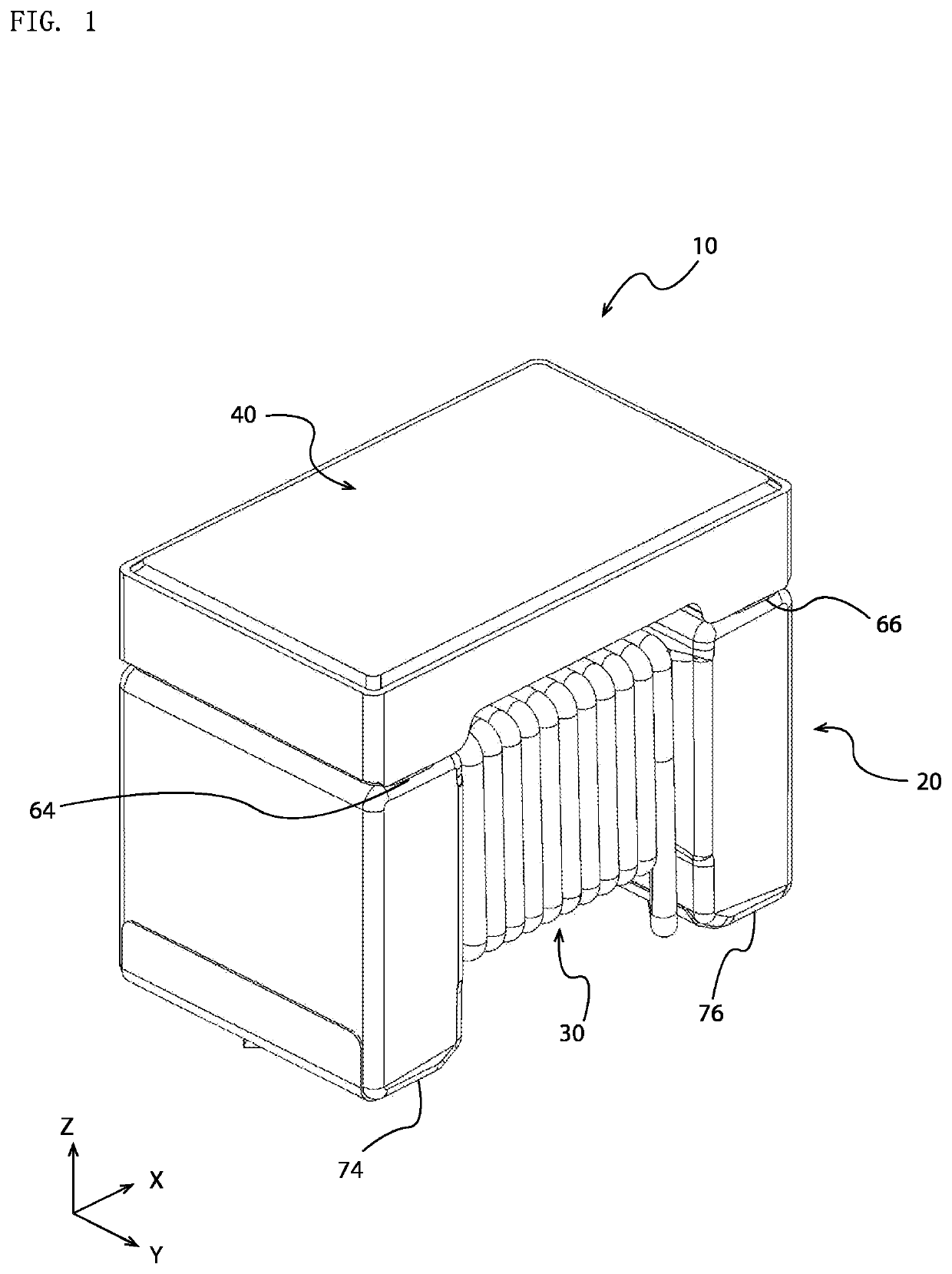
[0036]FIG. 1 is a perspective view in which a coil device 10 according to an embodiment of the invention is seen obliquely from above. The coil device 10 has a drum core 20, a coil 30, a plate core 40, a first electrode terminal 74, a second electrode terminal 76, and the like. The coil device 10 has a substantially rectangular parallelepiped outer shape. The coil device 10 is surface-mounted onto a mounting substrate by, for example, an adsorption nozzle of a mounting machine adsorbing, holding, and transporting the upper surface of the plate core 40. However, the coil device 10 is not limited to being surface-mounted.

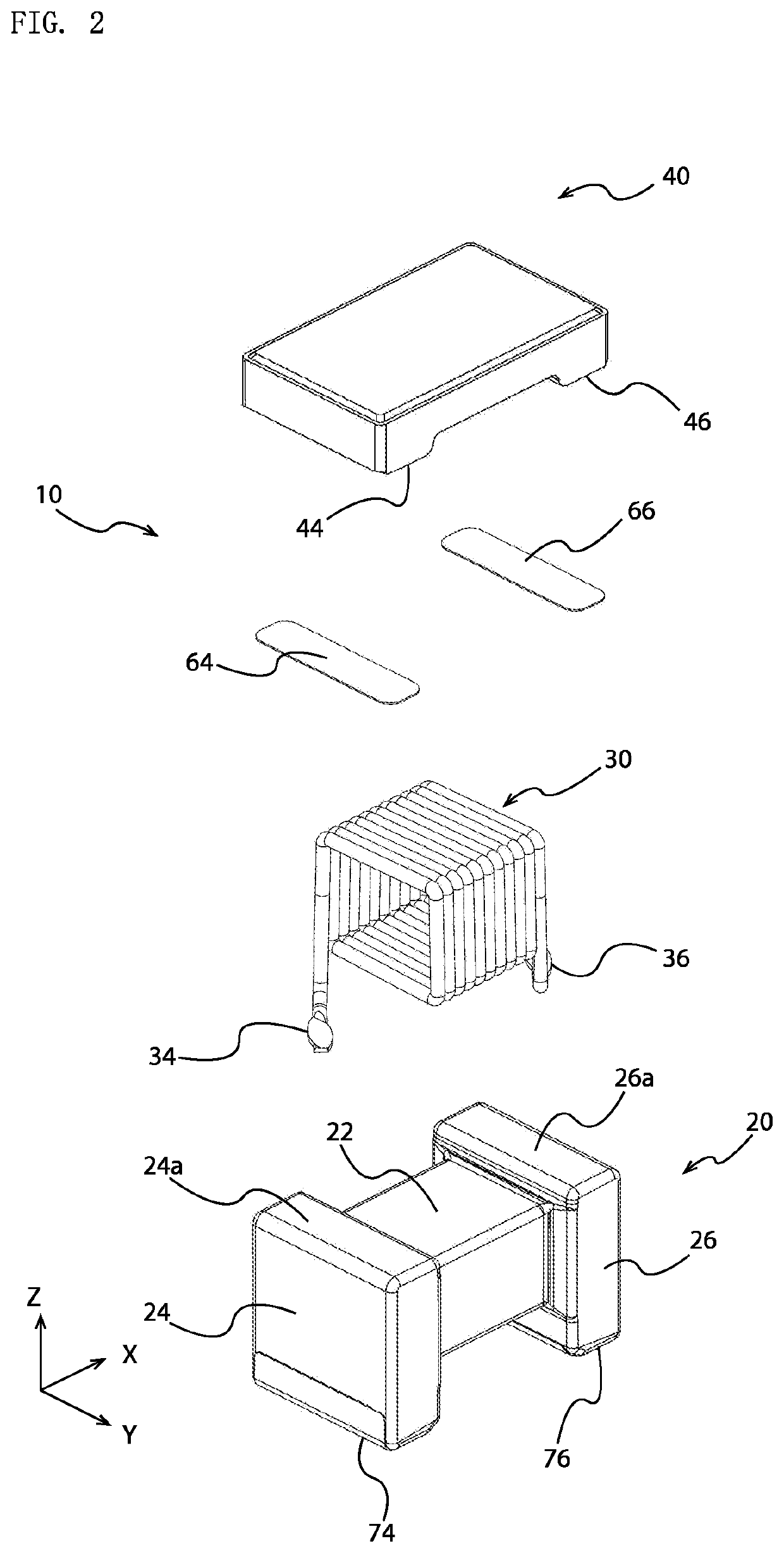
[0037]FIG. 2 is an exploded perspective view of the coil device 10 illustrated in FIG. 1. As illustrated in FIG. 2, the core of the coil device 10 is configured by the drum core 20 and the plate core 40 being bonded. The coil device 10 has a first cured-adhesive portion 64 and a second cured-adhesive portion 66, which are formed by the adhesive that bonds the plate co...


PUM

PropertyMeasurementUnit
lengthaaaaaaaaaa
adhesionaaaaaaaaaa
outer shapeaaaaaaaaaa

Abstract

A coil device includes: a drum core having first and second flange portions and a winding core portion therebetween; a coil wound around the core portion; a plate core connected to first and second flange portions first and second flange surfaces at a first direction side; a first electrode terminal on the first flange portion, one coil end portion electrically connected on the first electrode terminal; and a second electrode terminal on the second flange portion, the other coil end portion electrically connected on the second electrode terminal. The plate core has a first and second projecting portions respectively protruding toward the first and second flange surfaces and having first and second flat surfaces facing the first and second flange surfaces. The drum core and the plate core are connected by abutting and bonding the first and second flange surfaces against the first and second flat surfaces.

Description

BACKGROUND OF THE INVENTION1. Field of the Invention[0001]The present invention relates to a coil device that uses a core which is a combination of a plate core and a drum core.2. Description of the Related Art[0002]A coil device that uses a core which is a combination of a plate core and a drum core has been proposed as a surface-mountable chip-type coil device. The plate core is bonded with an adhesive or the like to a flange portion of the drum core. The plate core of the related art has a simple plate shape, is connected to two flange portions of the drum core, and forms a closed magnetic circuit together with the drum core (see JP 2002-329618 A).SUMMARY OF THE INVENTION[0003]However, in the core having the shape of the related art, a problematic decline in the bondability between the drum core and the plate core arises due to the material of the core or the like. For example, the bondability tends to decline in a case where the material of the plate core is not ferrite and the ...

Claims


Application Information

Patent Timeline
Patent Type & Authority Applications(United States)
IPC IPC(8): H01F27/24H01F27/29H01F41/04H01F41/02
CPCH01F27/24H01F27/29H01F1/344H01F41/0206H01F41/04H01F1/33H01F1/26H01F27/263H01F17/045H01F2003/103H01F27/255H01F27/292
Inventor SHINOHARA, RYOEIARASAWA, TAKASHIKAWASAKI, YOSHIHIRONISHIMURA, MUNEHITO
Owner TDK CORPARATION
Why Eureka
Try Eureka