Solid electrolyte capacitor and method for manufacturing the same

a technology of solid electrolyte capacitors and capacitors, which is applied in the direction of electrolytic capacitors, liquid electrolytic capacitors, variable capacitors, etc., can solve the problems of increasing resistance welding current and increasing the significance of problems, and achieves low cost, high dielectric constant, and prevent the effect of liquation of a core part of the valve metal substra

Active Publication Date: 2015-03-17
MURATA MFG CO LTD
View PDF6 Cites 0 Cited by
  • Summary
  • Abstract
  • Description
  • Claims
  • Application Information

AI Technical Summary

Benefits of technology

[0011]Thus, an object of the present invention is to provide a solid electrolytic capacitor which can solve the above-mentioned problems, namely a solid electrolytic capacitor in which a core part of a valve metal substrate does not liquate out, and bonding is provided between the valve metal substrate and a spacer with sufficient strength.
[0012]Another object of the present invention is to provide a method for manufacturing a solid electrolytic capacitor, wherein when a valve metal substrate and a spacer are bonded by resistance welding, control is performed so that a core part of the valve metal substrate does not liquate out.
[0015]In the solid electrolytic capacitor according to the present invention, the melting point of the bonding material provided in the spacer is preferably lower than the melting point of the valve metal substrate. Consequently the bonding material provided in the spacer more easily penetrates the etching part of the valve metal substrate, and consequently bondability between the valve metal substrate and the spacer can be further improved.
[0020]In a preferred embodiment of the present invention, the valve metal substrate is made of aluminum or an alloy having aluminum as a main component, the bonding material is made of tin or an alloy having tin as a main component, and the spacer is made of copper or an alloy having copper as a main component. According to the preferred embodiment, a solid electrolytic capacitor can be provided at a low cost, a high dielectric constant can be achieved in the valve metal substrate and the spacer, the handling characteristic of the valve metal substrate can be made satisfactory, and a difference of 400° C. or more in melting point can be provided between the valve metal substrate and the bonding material, and therefore, melting of only the bonding material can reliably achieved in the resistance melting step.
[0021]According to the present invention, when a spacer is bonded to a positive electrode part of a valve metal substrate, liquation of a core part of the valve metal substrate can be prevented. The melted bonding material can penetrate an etching part of the valve metal substrate to exhibit an anchor effect. Consequently, the bonding strength between the valve metal substrate and the spacer can be improved while suppressing a reduction in bonding strength of the valve metal substrate itself.

Problems solved by technology

Particularly, as the number of valve metal substrates 1 that are stacked is becomes larger, a current in resistance welding increases, and therefore this problem becomes more significant.

Method used


Image

  • Solid electrolyte capacitor and method for manufacturing the same
  • Solid electrolyte capacitor and method for manufacturing the same
  • Solid electrolyte capacitor and method for manufacturing the same

Examples


Embodiment Construction

[0030]A solid electrolytic capacitor 11 according to one embodiment of the present invention will be described with reference to FIGS. 1 to 3.

[0031]As shown in FIG. 1, the solid electrolytic capacitor 11 includes a laminate 13 constituted by stacking, for example, 4 capacitor units 12. The configurations of these 4 capacitor units 12 are common.

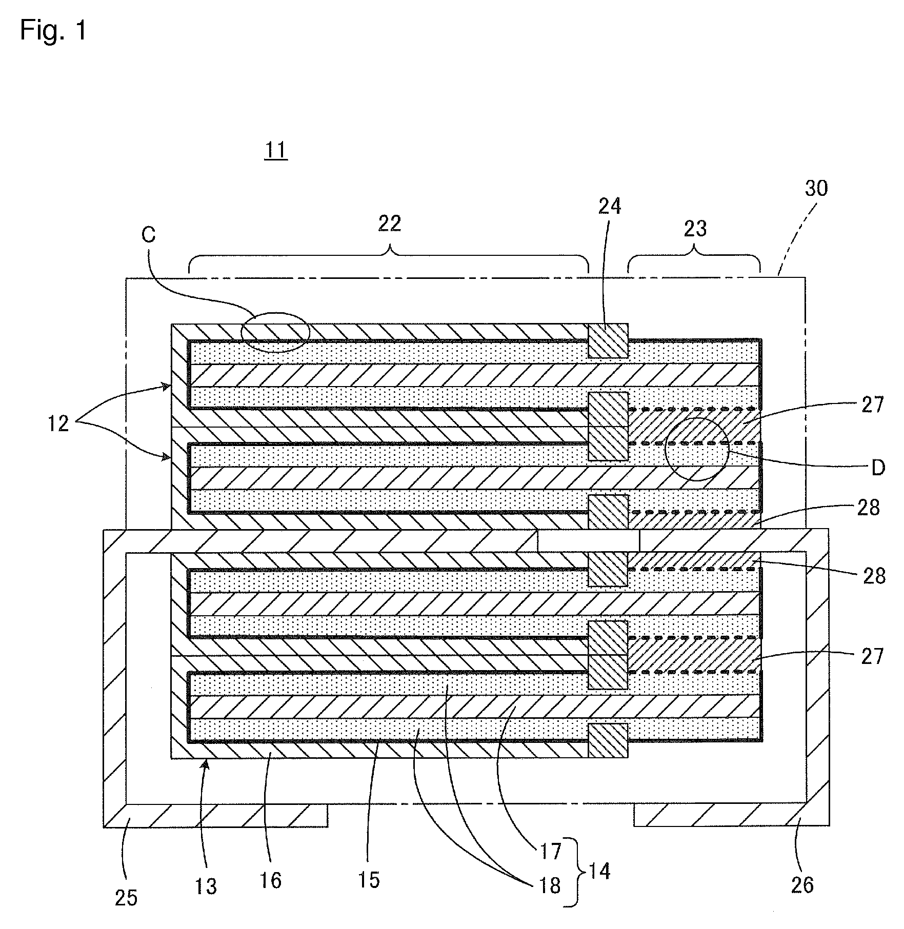
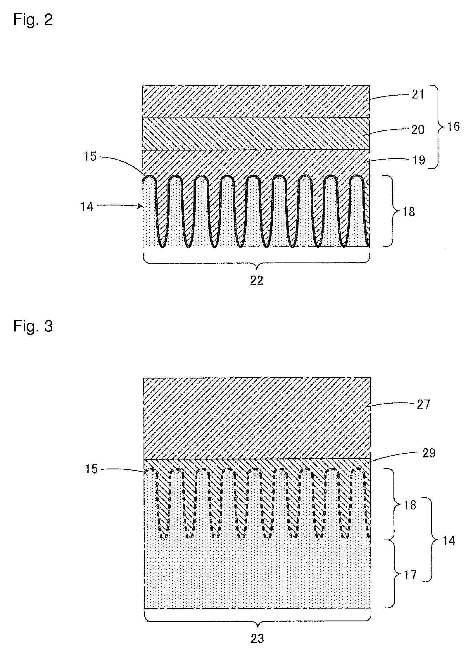
[0032]Each capacitor unit 12 includes a valve metal substrate 14, a dielectric film 15 (shown by a bold line in FIG. 1) formed on the surface of the valve metal substrate 14, and a negative electrode layer 16 formed on the dielectric film 15.

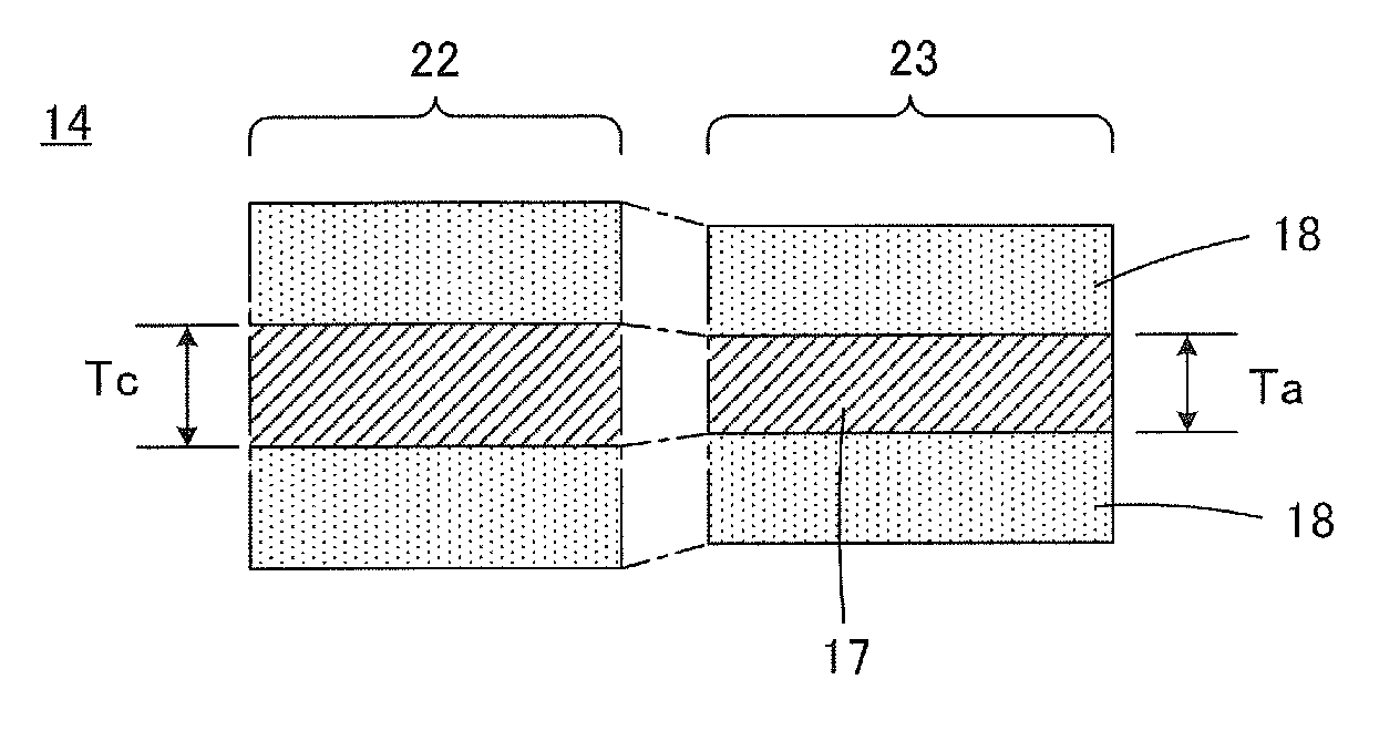
[0033]The valve metal substrate 14 is made of, for example, aluminum, tantalum or niobium, but is preferably made of aluminum or an alloy having aluminum as a main component. As one example, the valve metal substrate 14 is made of an aluminum foil, and is subjected to an etching treatment to thereby roughen the surface, and consequently has a core part 17 and an etching part 18 formed along the surface th...


PUM

PropertyMeasurementUnit
thicknessaaaaaaaaaa
melting pointaaaaaaaaaa

Abstract

In a solid electrolytic capacitor, resistance welding is carried out to bond a valve metal substrate and a spacer together while controlling a welding current so that only a bonding material provided in spacers and having a relatively low melting point is melted. At least a portion of the bonding material provided in the spacer penetrates an etching part of the valve metal substrate, and thickness Ta of a core part located at a positive electrode part in the valve metal substrate and thickness Tc of the core part located at a negative electrode part satisfy the requirement of |Tc−Ta| / Tc×100≦10[%].

Description

FIELD OF THE INVENTION[0001]The present invention relates to a solid electrolytic capacitor and a method for manufacturing the same, and particularly relates to a solid electrolytic capacitor in which a plurality of valve metal substrates are stacked to form a laminate, and a method for manufacturing the same.DESCRIPTION OF THE RELATED ART[0002]A solid electrolytic capacitor interesting for the present invention is described in, for example, International Publication WO 2006 / 129639 (International Publication WO 2006 / 129639). The solid electrolytic capacitor described in International Publication WO 2006 / 129639 includes a laminate constituted by stacking a plurality of valve metal substrates each having a core part and an etching part formed along the surface of the core part, and giving a positive electrode part and a negative electrode part.[0003]A dielectric film is formed on the surface of each valve metal substrate, and in the negative electrode part of the valve metal substrate...

Claims


Application Information

Patent Timeline
Patent Type & Authority Patents(United States)
IPC IPC(8): H01G9/00H01G9/012H01G9/14H01G9/15
CPCH01G9/012H01G9/15H01G9/14Y10T29/435
Inventor KITAYAMA, HIROKIKATSUBE, AKIO
Owner MURATA MFG CO LTD
Why Eureka
Try Eureka