Microfluidic devices and methods for manufacturing microfluidic devices

Pending Publication Date: 2021-03-11
CORNING INC
View PDF8 Cites 0 Cited by
  • Summary
  • Abstract
  • Description
  • Claims
  • Application Information

AI Technical Summary

Benefits of technology

[0033]The second glass layer can have a higher etch rate in the etchant than the first glass lay

Problems solved by technology

Conventional bio-analysis techniques employing these nucleic acid sequencing and single molecule assays often suffer fr

Method used


Image

  • Microfluidic devices and methods for manufacturing microfluidic devices
  • Microfluidic devices and methods for manufacturing microfluidic devices
  • Microfluidic devices and methods for manufacturing microfluidic devices

Examples


Embodiment Construction

[0045]Reference will now be made in detail to exemplary embodiments which are illustrated in the accompanying drawings. Whenever possible, the same reference numerals will be used throughout the drawings to refer to the same or like parts. The components in the drawings are not necessarily to scale, emphasis instead being placed upon illustrating the principles of the exemplary embodiments.

[0046]Numerical values, including endpoints of ranges, can be expressed herein as approximations preceded by the term “about,”“approximately,” or the like. In such cases, other embodiments include the particular numerical values. Regardless of whether a numerical value is expressed as an approximation, two embodiments are included in this disclosure: one expressed as an approximation, and another not expressed as an approximation. It will be further understood that an endpoint of each range is significant both in relation to another endpoint, and independently of another endpoint.

[0047]The term “s...


PUM

PropertyMeasurementUnit
Lengthaaaaaaaaaa
Lengthaaaaaaaaaa
Dimensionless propertyaaaaaaaaaa

Abstract

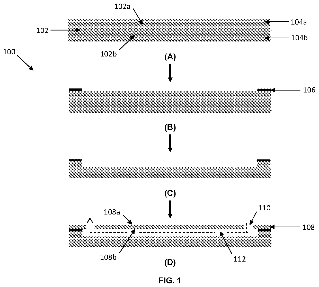
A method for manufacturing a microfluidic device (100) includes depositing a bonding layer (106) on a surface of a second glass layer (104a) of a glass substrate having a first glass layer (102) and the second glass layer (104a) fused to the first glass layer (102), such that a masked region of the surface is covered by the bonding layer, and an exposed region of the surface is uncovered by the bonding layer; removing a portion of the second glass layer corresponding to the exposed region of the surface to form a flow channel (112) in the glass substrate; and bonding a cover (108) to the glass substrate with the bonding layer (106).

Description

CROSS-REFERENCE TO RELATED APPLICATIONS[0001]This application claims the benefit of priority under 35 U.S.C. § 119 of U.S. Provisional Application No. 62 / 664,000, filed Apr. 27, 2018, the content of which is incorporated herein by reference in its entirety.BACKGROUND1. Field[0002]This disclosure relates to microfluidic devices and methods for manufacturing microfluidic devices.2. Technical Background[0003]Microfluidic devices may be useful for a variety of applications including bio-analysis (e.g., nucleic acid sequencing, single molecule analysis, etc.). In one example, the analysis is conducted by employing high resolution fluorescence imaging techniques to identify and quantify specific molecules at a surface of a substrate that is exposed to the microfluidic channel of the device. For instance, in optical detection based parallel gene sequencing techniques, millions of DNA fragments generated from a genomic DNA sample may be immobilized and partitioned onto the substrate surface...

Claims


Application Information

Patent Timeline
IPC IPC(8): B01L3/00
CPCB01L3/502715B01L3/502707B01L2300/161B01L2200/027B01L2200/12B01L2300/168B01L2300/12C03C15/02C03C27/10C03C27/08
Inventor FANG, YEKIM, JIN SULI, AIZE
Owner CORNING INC
Why Eureka
Try Eureka