
Manufacturing method of array substrate, array substrate and display device

A technology for array substrates and manufacturing methods, applied in the field of array substrates and display devices, capable of solving problems such as etching and damaging metal pattern layers

Active Publication Date: 2020-11-10
BOE TECH GRP CO LTD +1
View PDF4 Cites 0 Cited by
  • Summary
  • Abstract
  • Description
  • Claims
  • Application Information

AI Technical Summary

Problems solved by technology

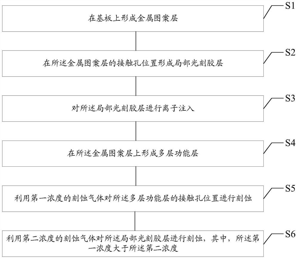
This method can solve the technical problem that the dry etching gas etch damages the metal pattern layer in the related art to a certain extent

Method used


Image

  • Manufacturing method of array substrate, array substrate and display device
  • Manufacturing method of array substrate, array substrate and display device
  • Manufacturing method of array substrate, array substrate and display device

Examples


Embodiment Construction

[0042] Example embodiments will now be described more fully with reference to the accompanying drawings. Example embodiments may, however, be embodied in many forms and should not be construed as limited to examples set forth herein; rather, these embodiments are provided so that this disclosure will be thorough and complete, and will fully convey the concept of example embodiments to those skilled in the art. The same reference numerals in the drawings denote the same or similar structures, and thus their detailed descriptions will be omitted.

[0043] Although relative terms such as "upper" and "lower" are used in this specification to describe the relative relationship of one component of an icon to another component, these terms are used in this specification only for convenience, for example, according to the description in the accompanying drawings directions for the example described above. It will be appreciated that if the illustrated device is turned over so that i...


PUM


Abstract

The invention relates to the field of display technology, and provides a method for manufacturing an array substrate. The method includes: forming a metal pattern layer on a substrate; forming a partial photoresist layer at the position of a contact hole in the metal pattern layer, and the contact hole is used to connect the metal pattern layer to a source or drain of an oxide thin film transistor pole; performing ion implantation on the local photoresist layer; forming a multi-layer functional layer on the metal pattern layer; using the first concentration of etching gas to etch the contact hole position of the multi-layer functional layer; The partial photoresist layer is etched with an etching gas of a second concentration, wherein the first concentration is greater than the second concentration. The manufacturing method of the array substrate provided in the present disclosure can avoid damage to the metal pattern layer by high-concentration etching gas.

Description

technical field [0001] The present invention relates to the field of display technology, in particular to a method for manufacturing an array substrate, the array substrate and a display device. Background technique [0002] In an OLED display device, the top gate arrangement of a thin film transistor (TFT) has higher on-state current, higher aperture ratio and better stability than the bottom gate arrangement. In the top-gate configuration of the thin film transistor, in order to protect the stability of the channel layer, a metal pattern layer is usually formed under the TFT to avoid external light from interfering with its characteristics. However, the charge accumulated on the metal pattern layer will affect the channel layer. Therefore, the metal pattern layer is usually connected to the drain or source of the TFT by setting a contact hole on the array substrate to lead out the metal pattern layer. charge. [0003] In the related art, dry etching gas is usually used t...

Claims


Application Information

Patent Timeline
Patent Type & Authority Patents(China)
IPC IPC(8): H01L21/768H01L27/12H01L27/32
CPCH01L27/1214H01L21/76897H10K59/12
Inventor 刘军周斌李伟胡迎宾方金钢郝朝威罗标
Owner BOE TECH GRP CO LTD
Learn More