Electrocaloric cooling with electrostatic actuation

a technology of electrostatic actuation and electrostatic cooling, which is applied in the direction of electrochemical generators, lighting and heating apparatus, and machine operation modes, etc., can solve the problems of difficult scaling down to meet the cooling demands of modern technologies, bulky, and complex vapor compression systems, etc., and achieve controllable increase (or decrease) of thermal contact and heat flux

Active Publication Date: 2021-03-11
SRI INTERNATIONAL +1
View PDF0 Cites 17 Cited by
  • Summary
  • Abstract
  • Description
  • Claims
  • Application Information

AI Technical Summary

Benefits of technology

[0009]The present disclosure describes solid state heat transporting devices comprising a heat transporting element whose uniformity of contact with one or multiple surfaces is controllable so that various amounts of heat may be transported to and from the one or multiple surfaces. The heat transporting element uses the electrocaloric effect to absorb and release the heat and the uniformity of contact is controlled using an electrostatic effect which may change the shape or position of the heat transporting element. The solid-state heat transporting device may be conformable to a flat or a non-flat surface and controllably increases (or decreases) thermal contact and heat flux between the device and the surface(s). In various examples, the heat transporting element(s) are incorporated into tiles used to cover and conform to various surfaces.

Problems solved by technology

While effective for many applications, vapor-compression systems have their disadvantages.
They are bulky, complex, and difficult to scale down to meet the cooling demands of modern technologies, such as mobile devices, wearable electronics, and flexible electronics.
(1,2) Existing refrigerants also have high global warming potentials, and present an environmental risk upon leaking or improper disposal.
However, these systems typically exhibit a COP even lower than that of vapor-compression refrigeration systems.
(4) Further, the ceramic materials tend to be expensive, restricting their use to small-scale applications.
Even though numerous publications have reported high material-level performances, the realization of functional solid-state cooling devices based on the EC effect remains a major challenge.
One practical challenge of implementing EC cooling devices stems from the fact that electrocaloric materials need to be physically transported between a heat sink and the heat source in sync with the application and removal of electric fields.
An electric motor and transmission may be used, but such a design lowers the COP and increases the size and overall complexity of the system.

Method used


Image

  • Electrocaloric cooling with electrostatic actuation
  • Electrocaloric cooling with electrostatic actuation
  • Electrocaloric cooling with electrostatic actuation

Examples


first embodiment

[0059]The present disclosure describes an EC refrigeration device architecture where electrostatic actuation is employed to (e.g., rapidly) transport a flexible EC polymer film or stack between a heat source and a heat sink. The electrostatic force not only moves the EC material but promotes the formation of (e.g., intimate) thermal contact between the EC polymer film or stack and the heat source / sink during each cycle.

first example

1. First Example

[0060]a. Architecture and Fabrication

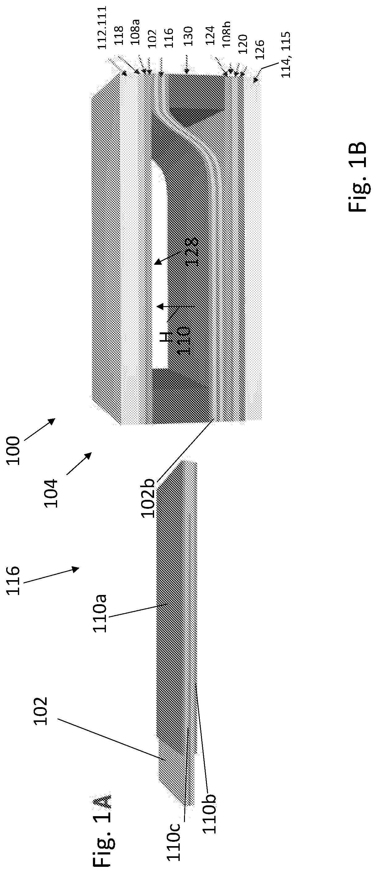
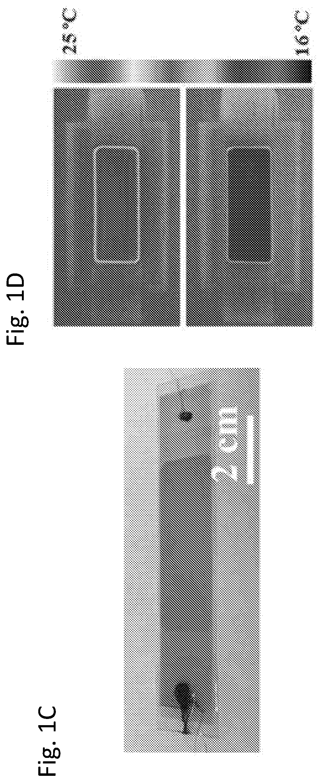
[0061]FIGS. 1A-1D illustrate the architecture of an EC cooling device 100 according to one example, comprising one or more heat transporting elements 102 and an actuation mechanism 104 attached to, coupled to, or on the heat transporting element(s). The heat transporting element(s) 102 each comprise a layer 102b of electrocaloric material or polymer and the actuation mechanism includes a first electrode layer 108a, and a second electrode layer 108b, and one or more flexible electrode layers 110. The first electrode layer 108a is attached to a heat sink 111 or through a plate 112 to the heat sink 111, the second electrode layer 108b is attached to a heat source 115 or through plate 114 to the heat sink 115, and the one or more flexible electrode layers 110 are attached to the one or more heat transporting elements (102).

[0062]In one or more examples, the heat transporting elements 102 and flexible electrode layers 108c are disposed...

second example

2. Second Example

[0117]FIG. 11 illustrates an alternative to S-shaped actuation comprising a device 1100 wherein curved surfaces 1102a, 1102b ensure good thermal contact when a flexible electrocaloric polymer layer 1104 is electrostatically attracted to the surface 1102a, 1102b and oscillates 1106 back and forth between the curved surfaces 1102a, 1102b. In this example, the device 1100 includes an electrocaloric polymer 1104 (including a single layer o stack) attached to flexible electrodes 1108, a source 1110 of cold or heat (cold source or heat source) having a curved surface 1112, a heat sink 1114 having a curved surface 1116, a first electrode 1118 on the curved surface 1112 of the cold source, a second electrode 1120 on the curved surface 1116 of heat sink 1114, a first insulator 1122 on the first electrode 1118, and a second insulator 1124 on the second electrode 1120. The heat transporting element 1150 may comprise the EC polymer 1104 alone or the EC polymer 1104 combined wit...


PUM


Abstract

A solid-state heat transporting device including a heat transporting element whose uniformity of contact with one or multiple surfaces is controllable so that various amounts of heat may be transported to and from the one or multiple surfaces. The heat transporting element uses the electrocaloric effect to absorb and release the heat and the uniformity of contact is controlled using an electrostatic effect which may change the shape of the heat transporting element. In one embodiment, the heat transporting element is an electrostatically actuated P(VDF-TrFE-CFE) polymer stack achieving a high specific cooling power of 2.8 W/g and a COP of 13 (the highest reported coefficient of performance to date) when used as a cooling device.

Description

CROSS REFERENCE TO RELATED APPLICATIONS[0001]This application claims the benefit under 35 U.S.C. Section 119(e) of co-pending and commonly-assigned U.S. Provisional Patent Application Ser. No. 62 / 502,251, filed on May 5, 2017 by Qibing Pei, Rujun Ma, Ziyang Zhang, Roy Kornbluh, and David Huber, entitled “ELECTROCALORIC COOLING WITH ELECTROSTATIC ACTUATION,” client reference number 2017-646, which application is incorporated by reference herein.STATEMENT REGARDING FEDERALLY SPONSORED RESEARCH AND DEVELOPMENT[0002]This invention was made with Government support under DE-AR0000532, awarded by the U.S. Department of Energy, and FA9550-12-1-0074, awarded by the U.S. Air Force, Office of Scientific Research. The Government has certain rights in the invention.TECHNICAL FIELD[0003]This invention relates to devices for transporting heat including, but not limited to, heating and cooling systems.BACKGROUND OF THE INVENTION[0004]Vapor-compression refrigeration systems, commonly used in air-con...

Claims


Application Information

Patent Timeline
Patent Type & Authority Applications(United States)
IPC IPC(8): F25B21/00H01L37/02
CPCF25B21/00F25B2321/001H01L37/025H01M10/6572H01M10/613H01M10/623Y02E60/10H10N15/15
Inventor PEI, QIBINGMA, RUJUNZHANG, ZIYANGKORNBLUH, ROYHUBER, DAVID
Owner SRI INTERNATIONAL
Why Eureka
Try Eureka