
Fixed ratio traction or friction drive

a fixed ratio, drive technology, applied in the direction of friction gearings, belts/chains/gearings, friction gearings, etc., can solve the problems of reducing control performance, limiting the allowable speed, and introducing a large number of undesirable effects, so as to reduce the number of loading cycles, increase service life, and drive high ratio

Active Publication Date: 2021-03-18
VECTIS DRIVE INC
View PDF0 Cites 2 Cited by
  • Summary
  • Abstract
  • Description
  • Claims
  • Application Information

AI Technical Summary

Benefits of technology

The patent describes a way to create high ratio drives using speed adapters. This design can increase the lifespan of the elements under high loads because they experience fewer loading cycles. The drives can have two or three stages, but more stages can be used to achieve the desired ratio and lifespan. To improve performance, a circular groove can be added to the fixed frame to increase contact pressure between the rollers and the frame, which can help solidify the traction fluid.

Problems solved by technology

As with other toothed gear configurations however, a number of undesirable effects are introduced.
First, with teeth bending under load, some flexibility is added, reducing the control performance.
Moreover, because of the discontinuous nature of this meshing and associated rigidity fluctuation, noise and vibrations occur, limiting the allowable speed.
Furthermore, to allow proper function, some backlash must be introduced, further reducing control performance and positioning accuracy.
Their manufacturing however requires precision techniques that can be challenging and costly.
Unnecessarily overloading the contacts increases material fatigue and energy losses.
One of the challenging design aspects is therefore to provide and maintain adequate contact forces.
This has obvious benefits but also adds to the drive complexity, cost and potentially torsional flexibility.
Friction or traction contacts can be purely rolling or also present spin or sideslip.

Method used


Image

  • Fixed ratio traction or friction drive
  • Fixed ratio traction or friction drive
  • Fixed ratio traction or friction drive

Examples


Embodiment Construction

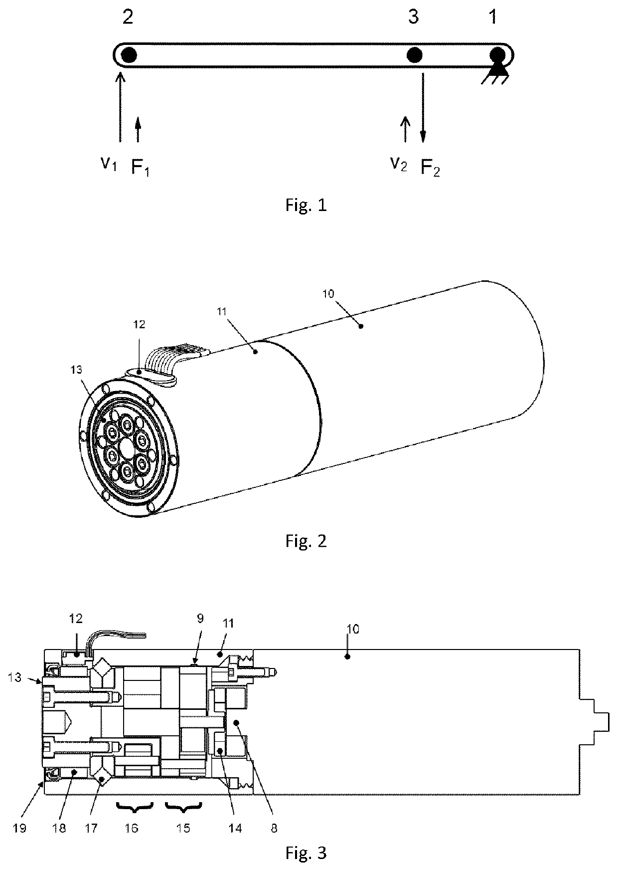
[0071]Referring to the prior art described above, some of the drawbacks most often encountered with toothed gears can be addressed by using a friction drive or a traction drive. Rather than contact between teeth, friction or traction drives rely on the friction or traction forces generated between smooth elements in rolling contact. Generally, a friction drive refers to a transmission with dry contacts while a traction drive refers to a transmission with lubricated contacts. As opposed to toothed gears, contacts are continuous (i.e., toothless), leading to significant opportunities to reduce noise, reduce vibrations, increase stiffness, run at higher speeds and eliminate backlash at the contact point.

[0072]Today, few fixed ratio speed adapters are commercially available. However, with continuously improving steel fatigue resistance, fluid traction properties, manufacturing techniques for rolling surfaces and position sensor technologies, fixed ratio traction or friction drives now s...


PUM


Abstract

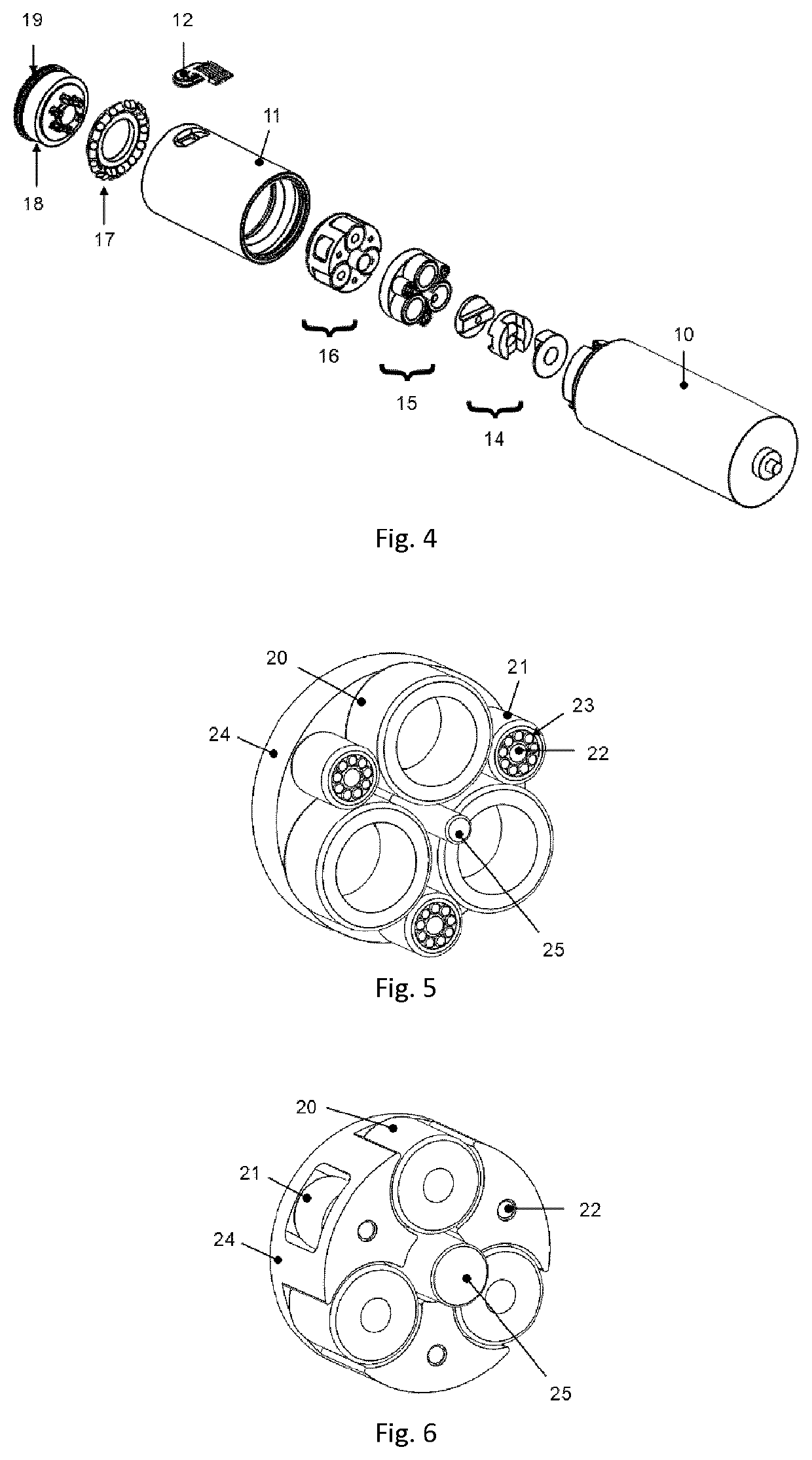
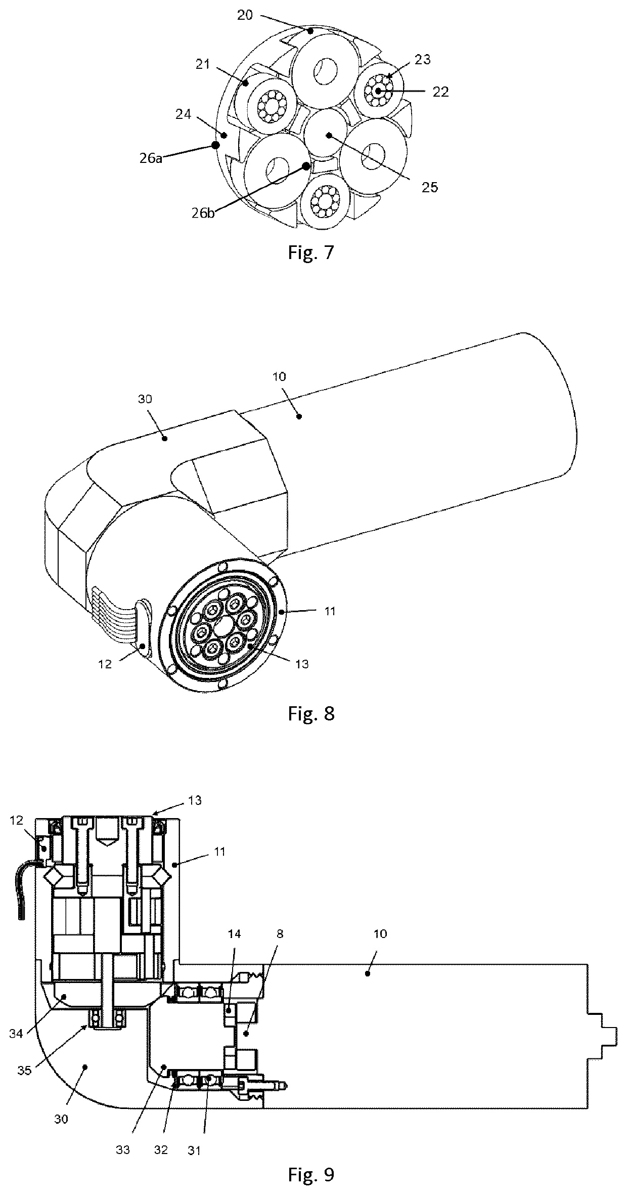
There is described a multistage friction / traction speed adapter. A first drive can include a plurality of free rollers orbiting around a sun element within a frame, transmitting their orbiting movement to guided rollers which do not contact the sun element or the frame. The guided rollers are driven in the orbiting movement and transmit the rotary movement to a carrier via corresponding pins which engage with the carrier. A second drive can include rollers having radial position variation which is prevented from being transmitted to the carrier by providing accommodation at the pin level, either by providing a bushing around the pins with a bore that is eccentric relative to its outer surface, either by engaging the pins into the carriers in portions thereof which are made more flexible. A friction / traction gear at an angle is also disclosed.

Description

CROSS-REFERENCE TO RELATED APPLICATIONS[0001]This application claims benefit or priority of U.S. provisional patent application 62 / 681,464, filed Jun. 6, 2018, which is hereby incorporated herein by reference in its entirety.BACKGROUND(a) Field[0002]The subject matter disclosed generally relates to traction or friction gears or drives. More specifically, it relates to a fixed-ratio drive.[0003](b) Related Prior Art[0004]In mechanical systems, rotary speed adapters can be used to adapt the torque and speed of the energy source to the load. For example, speed reducers are often used to increase the torque of electromagnetic motors. Another example is a machine tools spindle where, this time, a speed increase between the motor and the tool can be desirable.[0005]Today, most high-performance speed adapters rely on the meshing of toothed spur or helical gears. When a compact integration is desired, the epicyclic or planetary configuration is often selected. In this configuration, the loa...

Claims


Application Information

Patent Timeline
IPC IPC(8): F16H13/08F16H13/10
CPCF16H13/08F16H2057/085F16H13/10F16H13/06F16H57/082
Inventor FAUTEUX, PHILIPPE
Owner VECTIS DRIVE INC
Learn More