Coil formation in an electric machine with concentrated windings

a technology of concentrated windings and electric machines, which is applied in the direction of mechanical energy handling, stator/rotor body manufacturing, magnetic circuit shape/form/construction, etc., can solve the problems of reducing machine performance, difficult to insert coils with narrow coil width for side by side coil formation, and damage to coil insulation

Pending Publication Date: 2021-03-18
SIEMENS GAMESA RENEWABLE ENERGY AS
View PDF0 Cites 0 Cited by
  • Summary
  • Abstract
  • Description
  • Claims
  • Application Information

AI Technical Summary

Problems solved by technology

In such design the double layer winding layout makes it difficult to insert coils with narrow coil width for side by side coil formation.
Also, there is a possibility to damage the coil insulation during coil insertion process.
This

Method used


Image

  • Coil formation in an electric machine with concentrated windings
  • Coil formation in an electric machine with concentrated windings
  • Coil formation in an electric machine with concentrated windings

Examples


Embodiment Construction

[0038]The illustrations in the drawings are schematic. It is noted that in different figures, similar or identical elements are provided with the same reference signs.

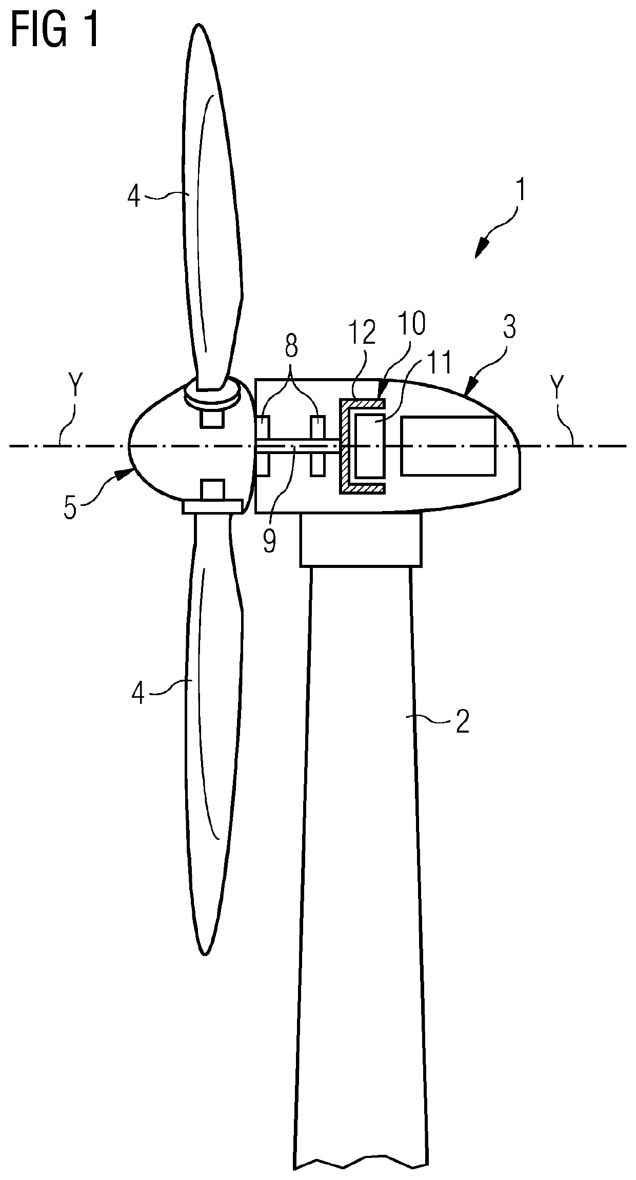
[0039]FIG. 1 shows a wind turbine 1 according to embodiments of the invention. The wind turbine 1 comprises a tower 2, which is mounted on a non-depicted fundament. A nacelle 3 is arranged on top of the tower 2.

[0040]The wind turbine 1 further comprises a wind rotor 5 having two, three or more blades 4 (in the perspective of FIG. 1 only two blades 4 are visible). The wind rotor 5 is rotatable around a rotational axis Y. When not differently specified, the terms axial, radial and circumferential in the following are made with reference to the rotational axis Y.

[0041]The blades 4 extend radially with respect to the rotational axis Y.

[0042]The wind turbine 1 comprises a concentrated winding electric generator 10.

[0043]The wind rotor 5 is rotationally coupled with the electric generator 10 by means of a rotatable main shaf...


PUM


Abstract

Provided is an electric generator including a stator including:
    • a stator yoke
    • a plurality of teeth,
    • a plurality of slots extending radially from the stator yoke to respective radial slot ends, the plurality of slots being circumferentially interposed between the teeth of the stator, each slot including a bottom portion adjacent to the stator yoke and a top portion adjacent to the respective radial slot end. The stator further includes a plurality of coils housed in the plurality of slots, each slot housing at least one coil in the bottom portion and at least another coil in the top portion, each coil housed in the bottom portion of a first slot of the plurality of slots being connected to another respective coil housed in the top portion of a second slot of the plurality of slots.

Description

CROSS-REFERENCE TO RELATED APPLICATIONS[0001]This application claims priority to PCT Application No. PCT / EP2019 / 058345, having a filing date of Apr. 3, 2019, which is based off of EP Application No. 18167999.4, having a filing date of Apr. 18, 2018, the entire contents both of which are hereby incorporated by reference.FIELD OF TECHNOLOGY[0002]The following relates to an electric machine with concentrated windings having a coil geometry permitting an increase of the fill factor, i.e. the ratio between the winding which is made of a good conducting material and the volume needed to house the winding.[0003]The following may be particularly, but not exclusively, applied to the electric generator of a wind turbine.BACKGROUND[0004]An electrical machine, such as an electric generator installed in a wind turbine, typically comprises a rotor which rotates relative to a stator.[0005]The stator normally comprises a frame body longitudinally extending along a longitudinal axis and including a ...

Claims


Application Information

Patent Timeline
IPC IPC(8): H02K1/16H02K15/02H02K3/12
CPCH02K1/165H02K7/183H02K3/12H02K15/024H02K3/487H02K7/1838Y02E10/72H02K1/148H02K3/18H02K15/022H02K15/063H02K1/2791
Inventor AZAR, ZIADGROENDAHL, ERIKSAMANTA, SUBHRATHOMAS, ARWYN
Owner SIEMENS GAMESA RENEWABLE ENERGY AS
Why Eureka
Try Eureka