Power conversion device

Active Publication Date: 2021-03-25
MITSUBISHI ELECTRIC CORP
View PDF0 Cites 8 Cited by
  • Summary
  • Abstract
  • Description
  • Claims
  • Application Information

AI Technical Summary

Benefits of technology

[0010]According to the embodiment, the semiconductor switching elements forming the bridge circuit can be used instead of a conventional bypass switch, and therefore, the volume of the cell converter and the cost can be suppressed. In the embodi

Problems solved by technology

When a failure occurs for some reason in one of converter cells formin

Method used


Image

  • Power conversion device
  • Power conversion device
  • Power conversion device

Examples


first embodiment

[0023][Schematic Configuration of Power Conversion Device]

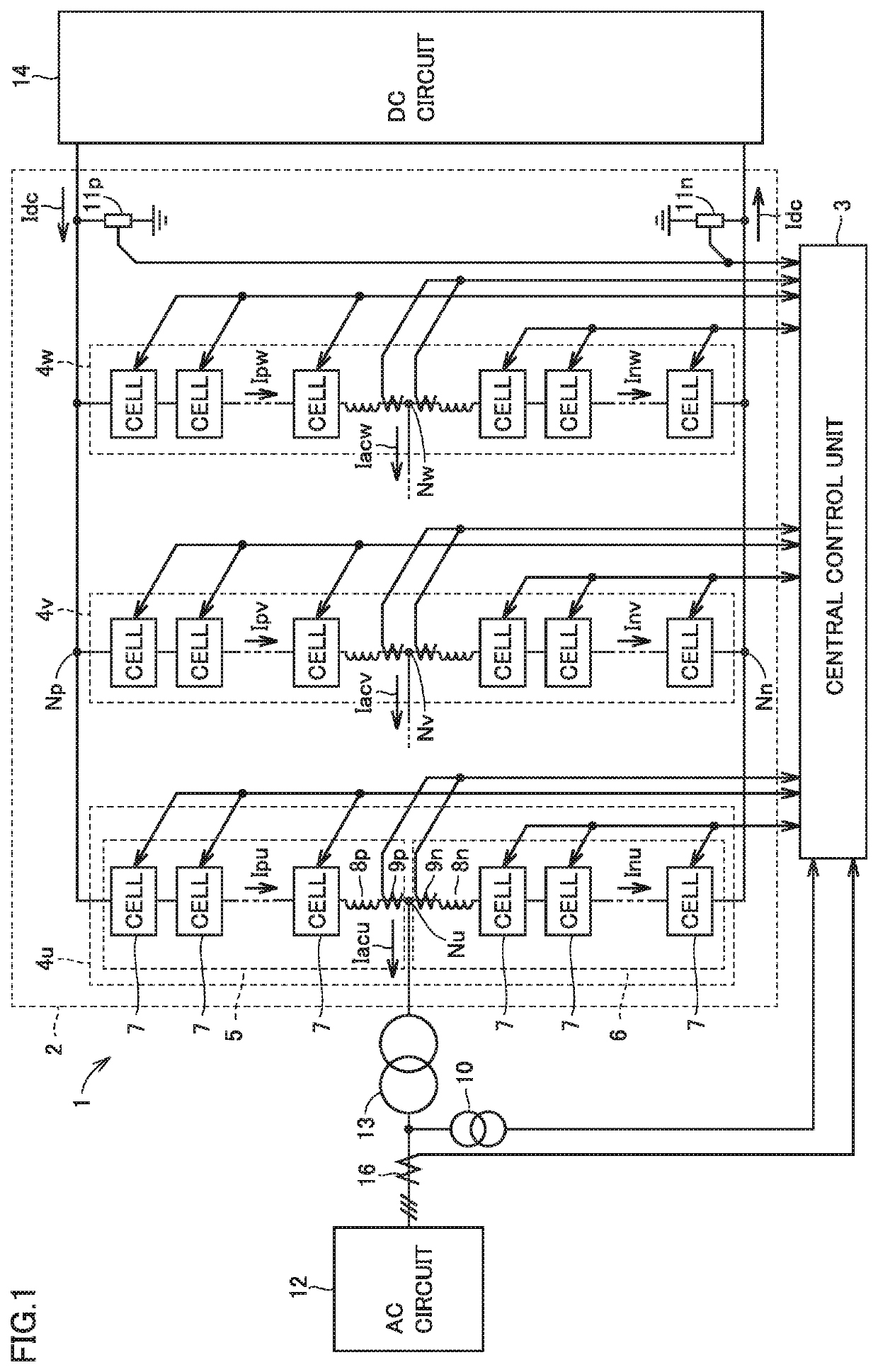
[0024]FIG. 1 shows a schematic configuration example of a power conversion device in a first embodiment. Referring to FIG. 1, a power conversion device 1 includes leg circuits 4u, 4v, 4w (which may be referred to non-specifically as leg circuit 4) that are main circuits, and a central control unit 3. The whole of leg circuits 4u, 4v, 4w is referred to as power conversion circuitry 2 in the present embodiment.

[0025]Leg circuit 4 is provided for each of a plurality of phases of AC, and connected between an AC circuit 12 and a DC circuit 14 for performing power conversion between the AC circuit and the DC circuit. AC circuit 12 shown in FIG. 1 is a three-phase AC circuit, and three leg circuits 4u, 4v and 4w are provided for U phase, V phase and W phase, respectively.

[0026]AC terminals Nu, Nv, Nw provided respectively in leg circuits 4u, 4v, 4w are each connected through an interconnection transformer 13 to AC circuit 12. AC cir...

second embodiment

[0100]In the first embodiment, each converter cell 7 is formed of half-bridge-type bridge circuit 30. In the following, each converter cell 7 formed of a full-bridge-type or three-quarter-type bridge circuit is described. Either circuit configuration produces similar effects to those of the first embodiment. In the following, the differences from the first embodiment are mainly described, and similarities are not described repeatedly.

[0101][Configuration of Full-Bridge-Type Bridge Circuit]

[0102]FIG. 9 shows another configuration example of a converter cell forming each leg circuit in FIG. 1. Converter cell 7 in FIG. 9 is different from converter cell 7 in FIG. 6 in that a full-bridge-type bridge circuit 30A is provided instead of half-bridge-type bridge circuit 30. In the following, the differences from bridge circuit 30 in FIG. 6 are mainly described, and similarities to the case of FIG. 6 are denoted by the same reference characters and are not described repeatedly.

[0103]Converter...

third embodiment

[0115]In a third embodiment, an example in which the power conversion device described in the first embodiment is applied to a reactive power compensation device referred to as a STATCOM (Static Synchronous Compensator) is described.

[0116]FIG. 11 shows a configuration example of a STATCOM of a Δ connection system. Referring to FIG. 11, a STATCOM 60 is configured such that arm circuits 61, 62, 63 each formed of a plurality of cascaded converter cells 7 are delta connected. Each of arm circuits 61, 62, 63 may be provided with a reactor 64 in series with converter cells 7. STATCOM 60 is connected through a transformer 65 to a transmission line 66 provided in AC circuit 12 (AC power system).

[0117]Each of converter cells 7 forming arm circuits 61, 62, 63 is configured as illustrated in FIG. 9 of the second embodiment. Thus, switching elements 35A, 35B, 41A, 41B forming the lower arm (i.e., second arm 34 and fourth arm 40) of full-bridge-type bridge circuit 30A can be used instead of a co...


PUM


Abstract

A power conversion device includes a plurality of cascaded converter cells. In each of the converter cells, each of a plurality of arms forming a bridge circuit is provided with a plurality of semiconductor switching elements in parallel. A drive controller of each of the converter cells is configured to, when none of a plurality of predetermined abnormality modes is detected, control the bridge circuit in accordance with an externally provided command. The drive controller is configured to, when at least one of the plurality of abnormality modes is detected, turn on all semiconductor switching elements provided in at least one of the plurality of arms forming the bridge circuit, to thereby establish a short circuit between first and second input/output nodes.

Description

TECHNICAL FIELD[0001]The present disclosure relates to a self-excited power conversion device formed of a plurality of cascaded converter cells, which is suitably used for, for example, high-voltage DC power transmission, a frequency converter, and a reactive power compensation device.BACKGROUND ART[0002]A modular multilevel converter (MMC) is known as a large-capacity power conversion device connected to an electric power system. The modular multilevel converter includes, for each phase of AC, an upper arm circuit connected to a high-potential-side DC terminal and a lower arm circuit connected to a low-potential-side DC terminal. Each arm circuit is formed of a plurality of cascaded converter cells.[0003]The converter cells are hereinafter also referred to as sub-modules.[0004]A converter cell includes a capacitor serving as an energy storage device, first and second input / output nodes, and a bridge circuit for switching between connection and disconnection between these input / outp...

Claims


Application Information

Patent Timeline
IPC IPC(8): H02M1/32H02M7/483H02M1/42H02M7/5387
CPCH02M1/32H02M7/483H02M2007/4835H02M7/53871H02M1/4208H02M7/48H02M7/4835
Inventor TAKAHASHI, TATSUYAHAYASHI, SHIGEO
Owner MITSUBISHI ELECTRIC CORP
Why Eureka
Try Eureka