Power converter and control method of power converter

a power converter and control method technology, applied in the field of power converters, can solve the problems of increasing the ringing or the occurrence of ripples at the time of switching, dcdc converter becomes a problem to be solved, becomes complicated and larger in size, and achieves the effect of simplifying the filter structure and reducing the size of the devi

Active Publication Date: 2021-04-01
HITACHI LTD
View PDF38 Cites 0 Cited by
  • Summary
  • Abstract
  • Description
  • Claims
  • Application Information

AI Technical Summary

Benefits of technology

[0009]Further, to achieve the above-described object, provided according to the present invention is a power converter including N switching units each including switching elements connected in series, rectifiers each configured to rectify an output of a corresponding one of the N switching units, a combiner configured to combine outputs of the rectifiers, and a controller configured to separately control a switching signal applied to each of the switching elements of the switching units. The controller performs control to cause, when a switching signal applied to one of the switching elements of each of the switching units makes a transition from a low level to a high level, a switching signal applied to another of the switching elements of each of the switching units to make a transition from a high level to a low level, performs control to cause, when the switching signal applied to the one of the switching elements of each of the switching units makes a transition from a high level to a low level, the switching signal applied to the other of the switching elements of each of the switching units to make a transition from a low level to a high level, and performs control to prevent, when neither of the controls is enabled, a rise of one of the switching signals and a rise of another of the switching signals from being synchronized with each other and prevent a fall of the one of the switching signals and a fall of the other of the switching signals from being synchronized with each other.
[0010]Furthermore, to achieve the above-described object, provided according to the present invention is a control method of a power converter including N switching units each including switching elements connected in series, rectifiers each configured to rectify an output of a corresponding one of the N switching units, a combiner configured to combine outputs of the rectifiers, and a controller configured to separately control a switching signal applied to each of the switching elements of the switching units. The control method includes causing the controller to perform control to cause, when a switching signal applied to one of the switching elements of each of the switching units makes a transition from a low level to a high level, a switching signal applied to another of the switching elements of each of the switching units to make a transition from a high level to a low level, perform control to cause, when the switching signal applied to the one of the switching elements of each of the switching units makes a transition from a high level to a low level, the switching signal applied to the other of the switching elements of each of the switching units to make a transition from a low level to a high level, and perform control to prevent, when neither of the controls is enabled, a rise of one of the switching signals and a rise of another of the switching signals from being synchronized with each other and prevent a fall of the one of the switching signals and a fall of the other of the switching signals from being synchronized with each other.
[0011]According to the present invention, it is possible to cancel ringings occurring in each switching unit and ripples occurring in the rectifiers, simplify a filter structure, and downsize the device.

Problems solved by technology

As described above, an increase in ringing at the time of switching or the occurrence of ripples under a configuration where a power converter such as an inverter or converter for use in industrial equipment or in-vehicle electric components is used as a DCDC converter becomes a problem to be solved.
Further, a filter for removing ringings or ripples becomes complicated and larger in size, so that downsizing and simplification of the filter becomes a problem to be solved.

Method used


Image

  • Power converter and control method of power converter
  • Power converter and control method of power converter
  • Power converter and control method of power converter

Examples


first embodiment

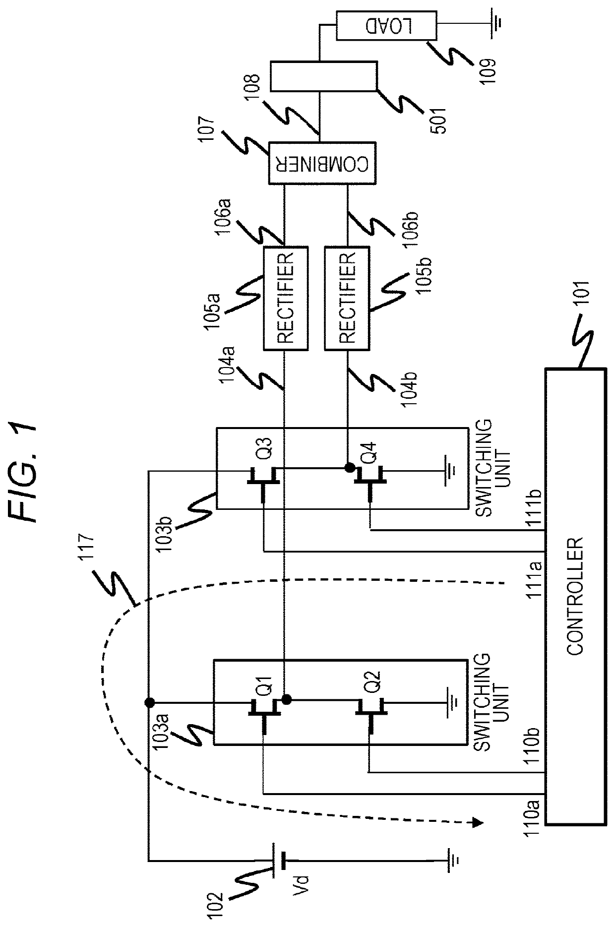
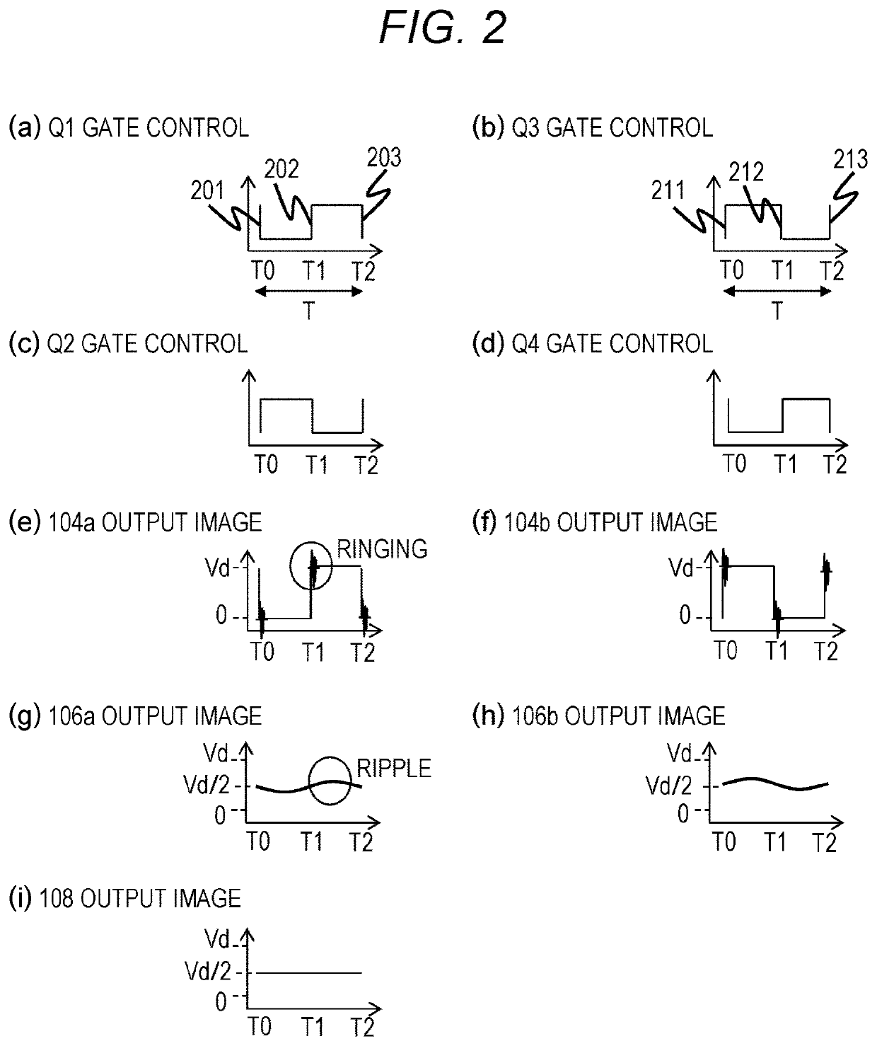
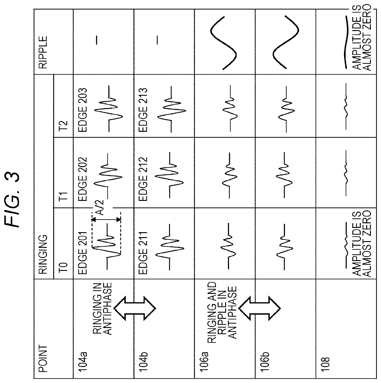
[0033]Provided according to the first embodiment is a power converter including N switching units each including switching elements connected in series, rectifiers each configured to rectify an output of a corresponding one of the N switching units, a combiner configured to combine outputs of the rectifiers, and a controller configured to separately control a switching signal applied to each of the switching elements of the switching units. The controller performs control to cause, when a switching signal applied to one of the switching elements of each of the switching units makes a transition from a low level to a high level, a switching signal applied to the other of the switching elements of each of the switching units to make a transition from a high level to a low level, and performs control to cause, when the switching signal applied to the one of the switching elements of each of the switching units makes a transition from a high level to a low level, the switching signal ap...

second embodiment

[0057]A power converter according to the second embodiment will be sequentially described with reference to FIGS. 8A to 8D. FIG. 8A shows a typical embodiment according to the second embodiment, and no description will be given of the same blocks and the same elements as shown in FIG. 1. The present embodiment is characterized in that buck-boost and rectification circuits 120a, 120b acting as rectifiers, that is, a Cockcroft-Walton (CW) circuit including transformers 121a, 121b, capacitors 123a, 123b, 124a, 124b, and diodes 122a, 122b, 124a, 124b are used, and it is possible to boost the voltage of the output 108 to a voltage higher than the power supply 102 and of course to a voltage lower than the power supply 102. Under the configuration according to the present embodiment, primary sides of the transformers 121a, 121b are connected to the power supply 102 via the capacitors 125a, 125b and are connected to the GND via the capacitors 126a, 126b, but the present invention is not lim...

third embodiment

[0062]A power converter corresponding to a typical embodiment according to the third embodiment will be described with reference to FIG. 9. In (a) of FIG. 9, no description will be given of the same blocks and the same elements as shown in FIG. 1. The power converter according to the present embodiment shown in (a) of FIG. 9 includes a combination of a push-pull circuit including a switching circuit 103a and a boost and rectification unit 130a, and a push-pull circuit including a switching circuit 103b and a boost and rectification unit 130b. That is, the switching units and the rectification units make up two sets of push-pull circuits, and a controller is an embodiment of the power converter that controls the two sets of switching units in an antiphase manner. Transformers 131a, 131b of the boost and rectification units 130a, 130b are disposed between drains of switching elements Q1, Q2 of the switching circuit 103a and between drains of switching elements Q3, Q4 of the switching ...


PUM


Abstract

A plurality of switching units are provided, and a controller performs control in an antiphase manner to approximately synchronize a rise of a control signal applied to one of the switching units with a fall of a control signal for switching applied to any one of the other switching units and synchronize a fall of the control signal applied to the one of the switching units with a rise of the control signal for switching applied to the any one of the other switching units. When control in an antiphase manner is disabled, control is performed to prevent rises or falls from coinciding with each other between the switching units. Output signals from the switching units are input to rectifiers and are combined by a combiner to become an output signal.

Description

CLAIM OF PRIORITY[0001]The present application claims priority from Japanese patent application JP 2019-175364 filed on Sep. 26, 2019, the content of which is hereby incorporated by reference into this application.BACKGROUND OF THE INVENTION1. Field of the Invention[0002]The present invention relates to a power converter such as an inverter or converter using a semiconductor element as a switch and a control method of the power converter.2. Description of the Related Art[0003]The pace of practical application of high-speed power electronics devices such as SiC / GaN is becoming faster. Power converters such as inverters or converters for use in industrial equipment or in-vehicle electric components are increasingly equipped with high-speed power electronics devices such as SiC / GaN that are small in size and high in efficiency, and an electromagnetic compatibility (EMC) design that reduces noise is becoming important.[0004]In particular, an increase in ringing occurring at the time of ...

Claims


Application Information

Patent Timeline
Patent Type & Authority Applications(United States)
IPC IPC(8): H02M3/335H02M1/14H02M1/44H03K17/16
CPCH02M3/33576H02M1/14H02M2001/0003H03K17/161H02M1/44H03K17/162H02M3/33571H02M3/33573Y02B70/10H02M1/0003H02M3/1584H02M3/1586H02M1/0043H02M3/33569H02M3/285
Inventor YAMAMOTO, AKIOLI, WENKADOI, RYO
Owner HITACHI LTD
Why Eureka
Try Eureka