Controller and control method for hybrid vehicle

Active Publication Date: 2021-04-08
TOYOTA JIDOSHA KK
View PDF0 Cites 4 Cited by
  • Summary
  • Abstract
  • Description
  • Claims
  • Application Information

AI Technical Summary

Benefits of technology

[0021]With the control method for a hybrid vehicle according to the second aspect, when downshift in the transmission is performed, as the upper-limit discharging electric power of the power storage device decreases, the rate of increase of the compressor rotation speed of the supercharger increases, the response delay of the supercharging pressure decreases, and the rate of increase of the engine torque increases. Accordingly, it is possible to curb an amount of assist torque of the rotary machine

Problems solved by technology

When a power storage device is subjected to a discharge limitation using upper-limit discharge electric power, necessary discharging electric power from the power storage device which is required for performing a downshift in a transmission may exceed the upper-limit discharging electric power.
However, in the controller described in JP 2015-214184 A, since the time required for progress of a downshift extends as the predicted electric power excess increases, deterioration in gear shift responsiveness may be caused.
When

Method used


Image

  • Controller and control method for hybrid vehicle
  • Controller and control method for hybrid vehicle
  • Controller and control method for hybrid vehicle

Examples


first embodiment

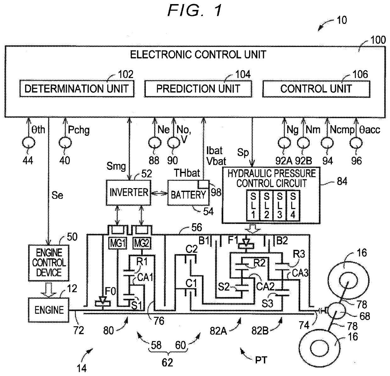
[0035]FIG. 1 is a diagram schematically illustrating a configuration of a hybrid vehicle 10 in which an electronic control unit 100 according to the disclosure is mounted and illustrating a principal part of a control function for various types of control in the hybrid vehicle 10. The hybrid vehicle 10 (hereinafter referred to as a “vehicle 10”) includes an engine 12, a first rotary machine MG1, a second rotary machine MG2, a power transmission device 14, and driving wheels 16.

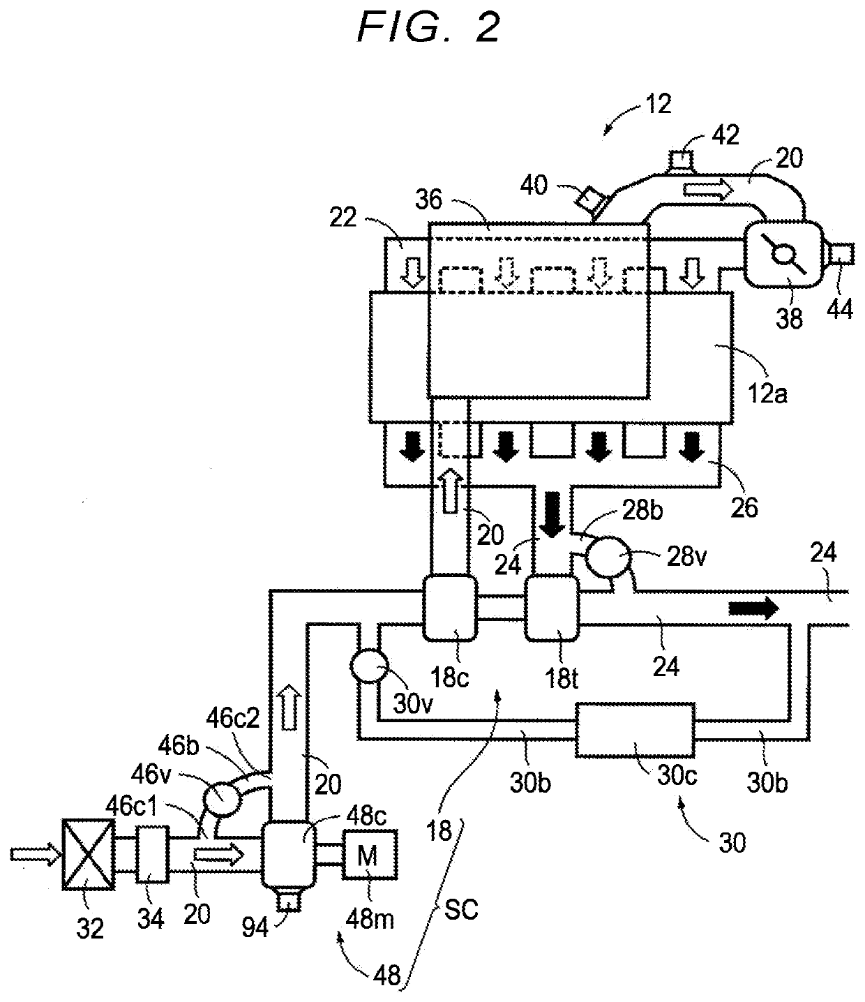
[0036]FIG. 2 is a diagram schematically illustrating a configuration of the engine 12. The engine 12 is a power source for travel of the vehicle 10 and is a known internal combustion engine such as a gasoline engine or a diesel engine including a supercharger SC, that is, an engine with the supercharger SC. The supercharger SC includes an exhaust turbine type supercharger 18 and an electric supercharger 48. An intake pipe 20 is provided in an intake system of the engine 12, and the intake pipe 20 is connected ...

second embodiment

[0129]The engine 12 and the rotary machine MG are drive power sources for travel of the vehicle 210 which are connected to the driving wheels 16 in a power-transmittable manner. The automatic transmission 262, the differential gear 68, and the axles 78 in the power transmission device 214 constitute the power transmission path PT provided between the engine 12 and the driving wheels 16 and between the rotary machine MG and the driving wheels 16. The rotary machine MG also has a function of a starter that cranks the engine 12 in a state in which the clutch K0 is engaged. The rotary machine MG in the second embodiment is an example of a “rotary machine” in the claims.

[0130]The clutch K0 is a hydraulic frictional engagement device that connects or disconnects transmission of power between the engine 12 and the rotary machine MG.

[0131]The automatic transmission 262 may be a stepped transmission and be, for example, a planetary gear type stepped transmission or a normally meshed type par...


PUM


Abstract

A controller for a hybrid vehicle predicts whether necessary discharging electric power from a power storage device which is required to perform downshift in a transmission exceeds upper-limit discharging electric power of the power storage device when downshift in the transmission is performed in a hybrid vehicle travel mode and controls a compressor rotation speed such that a rate of increase of the compressor rotation speed of a supercharger at the time of performing downshift in the transmission increases as the upper-limit discharging electric power decreases when it is predicted that the necessary discharging electric power exceeds the upper-limit discharging electric power.

Description

CROSS-REFERENCE TO RELATED APPLICATION[0001]This application claims priority to Japanese Patent Application No. 2019-182544 filed on Oct. 2, 2019, incorporated herein by reference in its entirety.BACKGROUND1. Technical Field[0002]The disclosure relates to a controller and a control method for a hybrid vehicle including an engine with a supercharger and a rotary machine as drive power sources for travel and including a transmission in a power transmission path between the engine and driving wheels and between the rotary machine and the driving wheels.2. Description of Related Art[0003]A controller for a hybrid vehicle including an engine with a supercharger, a rotary machine, and a power storage device that transmits and receives electric power to and from the rotary machine, using power which is output from the engine and the rotary machine as drive power for travel, and including a transmission in a power transmission path between the engine driving wheels and between the rotary ma...

Claims


Application Information

Patent Timeline
IPC IPC(8): B60W20/30B60W10/06B60W10/08B60W10/26B60W10/10F02B39/10
CPCB60W20/30B60W10/06B60W10/08B60W2510/244B60W10/10F02B39/10B60W2510/246B60W10/26B60W10/30B60W20/13B60W2510/0638B60W2510/081B60W2710/083B60W2510/0633B60W2710/0666B60K6/445B60K6/387B60K6/48B60K2006/4825B60K6/547B60K6/383B60K6/24B60W10/115B60W20/11B60W2710/0638B60W20/19Y02T10/70Y02T10/62B60W30/19B60W2510/248
Inventor OMURO, KEISUKETABATA, ATSUSHIKONO, TETSUYAOKUDA, KOICHI
Owner TOYOTA JIDOSHA KK
Why Eureka
Try Eureka