Vision inspection apparatus and a method of driving the same

a technology of inspection apparatus and inspection apparatus, which is applied in the direction of optical radiation measurement, instruments, television systems, etc., can solve the problems of saturation defect and decrease of correction accuracy, and achieve the effect of accurate calculation, decrease of correction accuracy, and increase of exposure tim

Active Publication Date: 2021-04-08
SAMSUNG DISPLAY CO LTD
View PDF0 Cites 0 Cited by
  • Summary
  • Abstract
  • Description
  • Claims
  • Application Information

AI Technical Summary

Benefits of technology

[0030]According to the embodiments, the vision inspection apparatus calculates an optimum exposure-time for obtaining a maximum charge amount for each gray level for the display panel. Therefore, the vision inspection apparatus may obtain an accurate reference gray level signal for the reference gray level displayed on the display panel. Accordingly, inspection correction values of the display panel may be accurately calculated.
[0031]In addition, the

Problems solved by technology

For example, when the charge amount of the charge-coupled device is insufficient, a display defect such as a mura may occur, and when the charge amount of the charge-coupled device is excessive, a saturation d

Method used


Image

  • Vision inspection apparatus and a method of driving the same
  • Vision inspection apparatus and a method of driving the same
  • Vision inspection apparatus and a method of driving the same

Examples


Embodiment Construction

[0039]Hereinafter, the inventive concept will be explained in more detail with reference to the accompanying drawings.

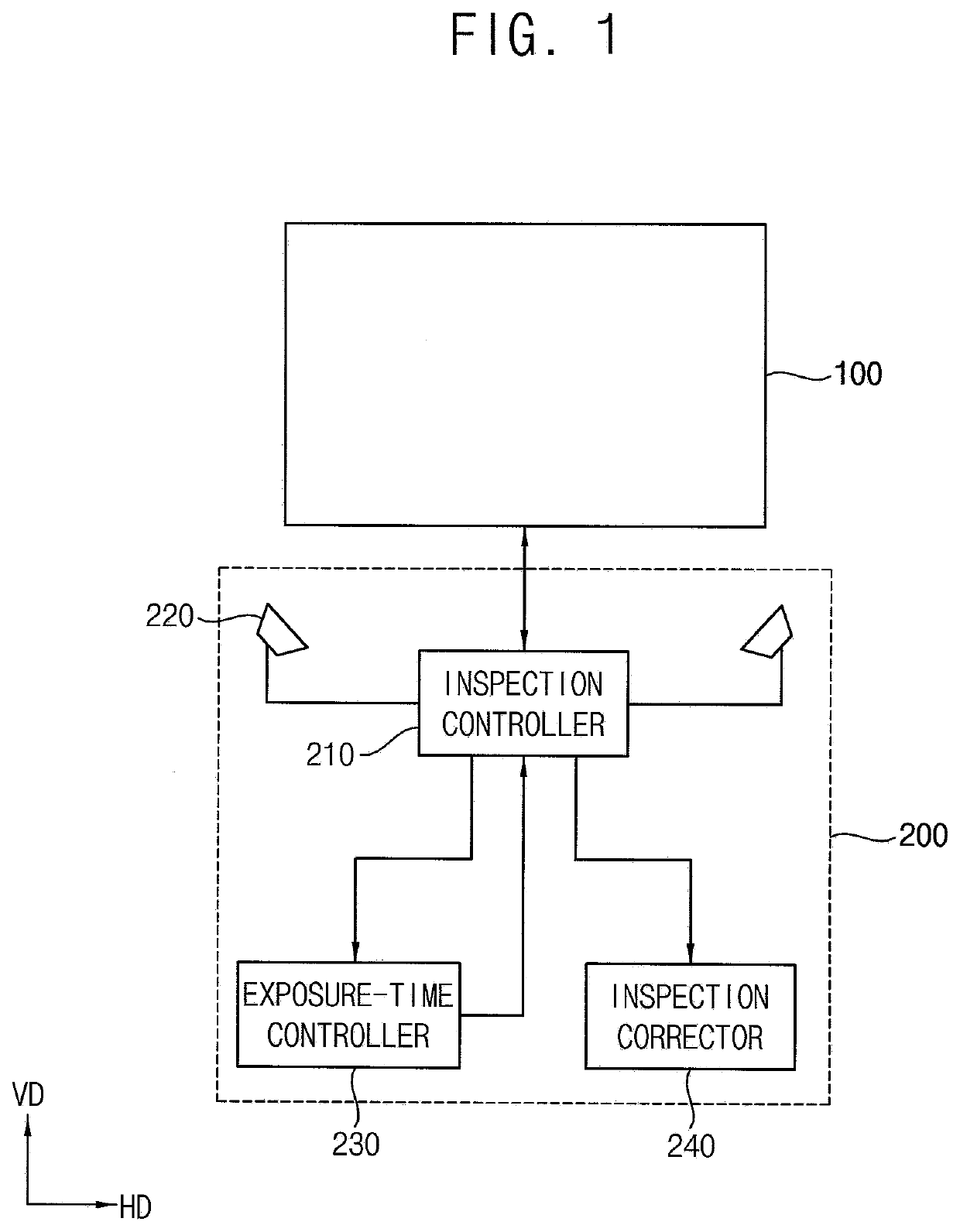
[0040]FIG. 1 is a schematic block diagram illustrating a vision inspection apparatus according to an embodiment.

[0041]Referring to FIG. 1, the vision inspection system includes a display panel 100 for inspection and a vision inspection apparatus 200 for inspecting the display panel 100.

[0042]The vision inspection apparatus 200 includes an inspection controller 210, an imaging converter 220, an exposure-time controller 230, and an inspection corrector 240.

[0043]The inspection controller 210 controls overall operation of the vision inspection apparatus 200.

[0044]The inspection controller 210 may display a plurality of reference gray levels on the display panel 100.

[0045]The plurality of reference gray levels may include a 255-gray level, a 192-gray level, a 128-gray level, a 96-gray level, a 64-gray level, a 32-gray level, a 24-gray level, a 16-gray level, and a 0-gray...


PUM


Abstract

A vision inspection apparatus includes an inspection controller which displays a grid pattern with a plurality of gray levels on a display panel, an imaging converter which drives a charge-coupled device with a predetermined or set exposure-time and converts the grid pattern displayed on the display panel into a grid pattern signal, a charge calculator which calculates a charge amount per unit time for each color of a reference gray level using a reference gray level signal, included in the grid pattern signal, and the set exposure-time, and an exposure-time calculator which calculates an optimum exposure-time for each color of the reference gray level based on a target charge amount of the reference gray level.

Description

CROSS-REFERENCE TO RELATED APPLICATION[0001]This application claims priority to and the benefit of Korean Patent Application No. 10-2018-0161531, filed on Dec. 14, 2018, which is hereby incorporated by reference for all purposes as if fully set forth herein.BACKGROUND1. Field[0002]The technical field relates to an inspection apparatus for defect inspection of a display panel and a method of driving the inspection apparatus.2. Description of the Related Art[0003]In general, a display panel (e.g., a display cell) for a liquid crystal display includes a lower substrate, an upper substrate facing the lower substrate, and a liquid crystal layer interposed between the lower substrate and the upper substrate. The lower substrate has a pixel area and a peripheral area to which a driving signal for driving the pixel area is applied.[0004]The pixel area includes a data line extending in a first direction and a gate line extending in a second direction and crossing the data line and a pixel el...

Claims


Application Information

Patent Timeline
IPC IPC(8): G01J3/50G09G3/36G01J1/42
CPCG01J3/506G09G3/36G09G2320/0242G09G2320/0233G01J1/4209G02F1/1309G01J1/4214G01J3/465G02F2203/30H04N17/002H04N25/534H04N25/71H04N23/84G01N21/95G01N2021/9513G01M11/0264G09G3/006H04N25/53
Inventor LEE, JUNEYOUNGMOON, HOI SIKYIM, HYUNGWOOCHUNG, JAE-SEOBCHAE, MINYUP
Owner SAMSUNG DISPLAY CO LTD
Why Eureka
Try Eureka