Opto-electronic assembly

Active Publication Date: 2021-04-08
HILIGHT SEMICON
View PDF0 Cites 1 Cited by
  • Summary
  • Abstract
  • Description
  • Claims
  • Application Information

AI Technical Summary

Benefits of technology

[0007]It is an object of the invention to provide means of construction and configuration for the receiving function of a high speed optical communication system wherein manufacturing cost is reduced compared with prior art.

Problems solved by technology

Such metal cans represent a significant proportion of the total cost of the ROSA.
Further, there is an inherent impediment to achieving the highest possible operating bandwidth since it is necessary for the high data rate o

Method used


Image

  • Opto-electronic assembly
  • Opto-electronic assembly
  • Opto-electronic assembly

Examples


Example

[0057]The description is not to be taken in a limiting sense but is made merely for the purposes of describing the general principles of the embodiments of the invention.

EMBODIMENTS OF THE APPLICATION

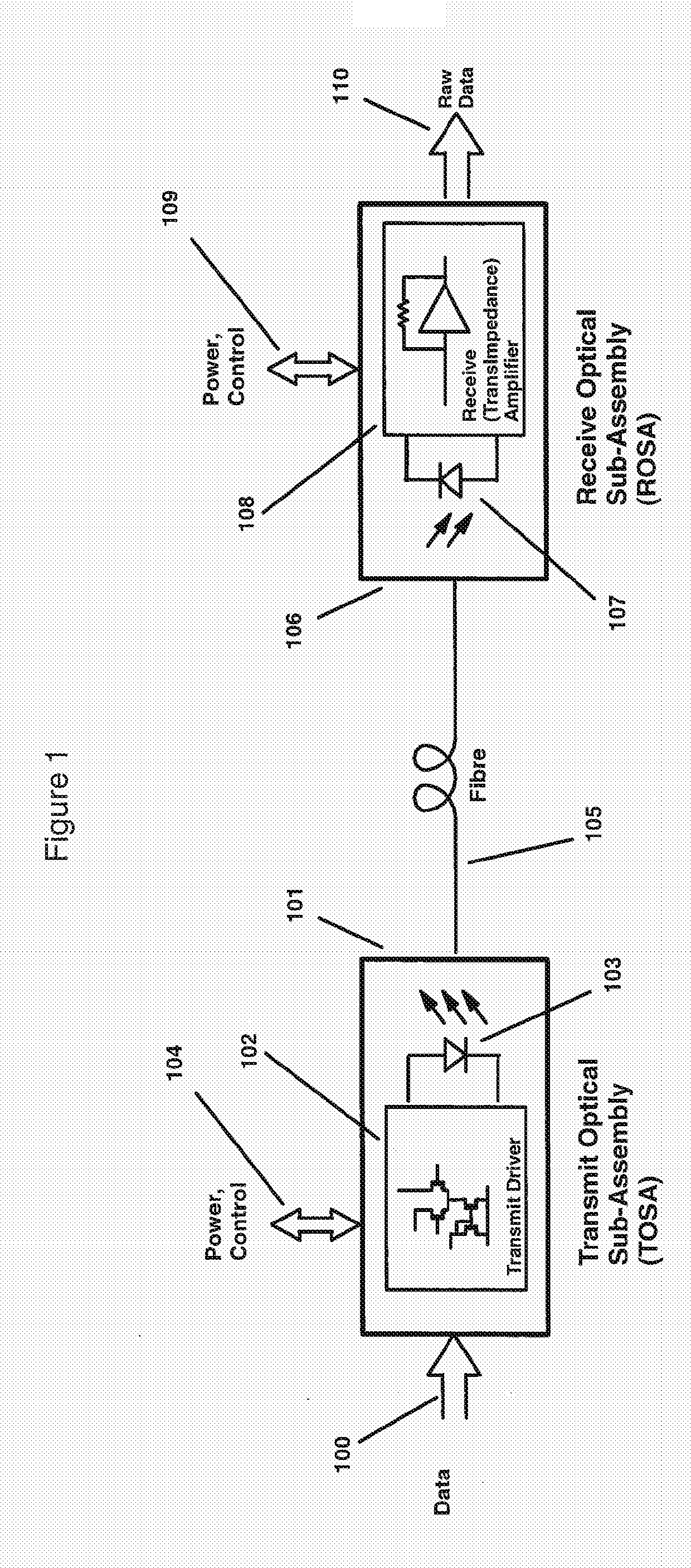
[0058]FIG. 1 shows the basic system level configuration of a generic optical communications physical link, wherein electrical data signals 100 containing information are converted to optical signals in a Transmit Optical Sub-Assembly (TOSA) 101, where said TOSA may be comprised of driver electronics 102 and typically a laser diode 103 or other electro-optical conversion device. The driver electronics provide the laser diode (or alternative device) with appropriate current waveforms necessary to create the desired optical signal representing the electrical data signals. There may be constraints imposed in order to respect further requirements imposed by agreed performance standards and specifications. The driver electronics may be a combination of components or have nearly all the necess...


PUM


Abstract

An assembly of electronic components enabling reception of data using an optical fiber includes: a photodiode; an amplifier coupled to the photodiode; a flexible printed circuit board, the photodiode and amplifier physically mounted on the flexible printed circuit board; a cover, the cover configured to cover the photodiode and the amplifier, wherein the cover is physically attached to the printed circuit board so as to provide mechanical rigidity around the photodiode, and the cover having an optically transparent aperture containing a lens configured to focus modulated light signals from a fiber onto the photodiode; and conductive bond wires configured to directly electrically couple the amplifier and the photodiode to conducting traces of the flexible printed circuit board.

Description

FIELD OF THE INVENTION[0001]The present application relates to opto-electronic assemblies and receive optical sub-assembly construction with chip-on-flex through-hold bonding.BACKGROUND OF THE INVENTION[0002]High speed optical communication links comprise many optical, electronic and opto-electronic components and assemblies wherein electrical signals are converted into optical signals for transmission over a fibre; and where optical signals conveyed by means of a fibre are converted to an electrical signal and subject to amplification and further processing. Common requirements for the components and assemblies used in such links are that the cost be minimised, while at the same time the performance is to be maximised.[0003]This invention is concerned with that part of an optical communications system wherein an optical signal is received and converted into an electrical signal and subject to amplification and possibly also subject to other signal processing functions before being ...

Claims


Application Information

Patent Timeline
IPC IPC(8): G02B6/42H05K1/18H05K1/11
CPCG02B6/4281G02B6/426H05K2201/10287H05K1/115H05K2201/10121H05K1/189G02B6/4204G02B6/424G02B6/423G02B6/24G02B6/4201H04B10/60
Inventor CARLEY, CARL
Owner HILIGHT SEMICON
Why Eureka
Try Eureka