
Patch antenna device

a technology of patch antenna and antenna device, which is applied in the direction of antenna, antenna details, simultaneous aerial operations, etc., can solve the problems of reducing restricting the size, and achieve the effect of increasing the degree of design freedom

Active Publication Date: 2021-04-15
HARADA IND CO LTD
View PDF0 Cites 3 Cited by
  • Summary
  • Abstract
  • Description
  • Claims
  • Application Information

AI Technical Summary

Benefits of technology

The present patent aims to provide a patch antennas device that utilizes a parasitic element to function as a wave director for the patch antenna, which will lead to a reduction in size and enhance design flexibility. The device is designed to make improvements in efficiency and performance.

Problems solved by technology

When an antenna like a low-profile antenna including a plurality of various antennas is accommodated in a case, it is restricted in size due to the limited space in the case.
This reduces the degree of freedom in design.

Method used


Image

  • Patch antenna device
  • Patch antenna device
  • Patch antenna device

Examples


Embodiment Construction

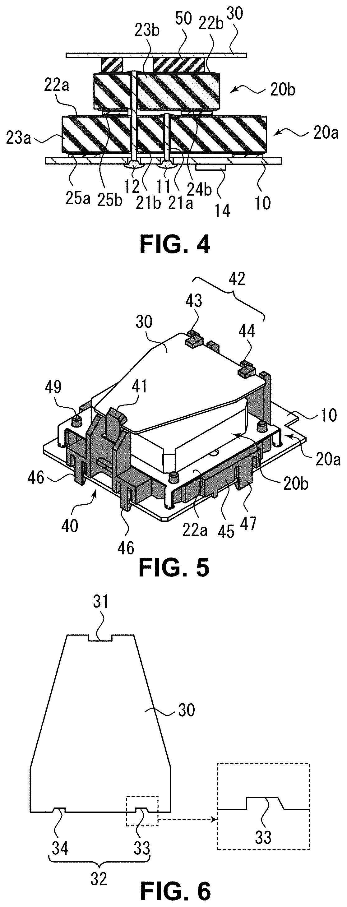
[0027]Preferred embodiments will be described below with reference to the accompanying drawings. FIG. 1 is a schematic perspective view for explaining a patch antenna device according to one illustrated embodiment. FIG. 2 is a schematic cross-sectional side view for explaining the patch antenna device according to the illustrated embodiment. FIG. 3 is a schematic top view for explaining the patch antenna device according to the illustrated embodiment. In FIGS. 2 and 3, the same reference numerals as those in FIG. 1 denote the same parts as those in FIG. 1. The patch antenna device according to the illustrated embodiment is configured to receive a radio communication signal. As illustrated, the patch antenna device according to the present disclosure mainly includes a circuit board 10, a patch antenna 20, and a parasitic element 30.

[0028]The circuit board 10 is a member on which a signal processing circuit is placed. A circuit pattern and a ground conductor pattern are formed by etch...


PUM


Abstract

A patch antenna device configured to receive a radio communication signal includes a circuit board, a patch antenna, and a parasitic element. The circuit board has a signal processing circuit placed thereon. The patch antenna is stacked on the circuit board and has a quadrangular radiation element. The parasitic element is disposed above the patch antenna so as to improve antenna gain characteristics of the patch antenna and configured such that the length of the upper side of the parasitic element is shorter than the width in a plan view of the radiation element of the patch antenna and that the length between the upper and lower sides of the parasitic element is longer than the length between the upper and lower sides of the radiation element of the patch antenna.

Description

CROSS-REFERENCE TO RELATED APPLICATIONS[0001]This application claims priority to Japanese Patent Application No. 2019-186574 filed on Oct. 10, 2019.BACKGROUNDTechnical Field[0002]The present invention generally relates to a patch antenna device, and more particularly to a patch antenna device with improved antenna gain characteristics.Description of the Related Art[0003]There is known a patch antenna for receiving a circularly polarized signal, which is constructed using a ceramic or dielectric substrate. Such a modularized patch antenna is accommodated in a low-profile antenna device mounted on a vehicle roof, for example, so as to realize communication such as GNSS (Global Navigation Satellite System) and SDARS (Satellite Digital Audio Radio Service). The low-profile antenna device includes, in addition to the patch antenna, antennas required to realize other communications, such as radio, television, and mobile phone.[0004]Further, there is known an antenna device in which a para...

Claims


Application Information

Patent Timeline
Patent Type & Authority Applications(United States)
IPC IPC(8): H01Q9/04H01Q19/00H01Q5/378
CPCH01Q9/0407H01Q5/378H01Q19/005H01Q9/0414H01Q9/0428H01Q5/40H01Q1/38H01Q1/3233H01Q1/3275
Inventor HASEGAWA, RYOHEI
Owner HARADA IND CO LTD
Learn More