Gauge

Inactive Publication Date: 2021-04-29
ROLLS ROYCE PLC
View PDF10 Cites 1 Cited by
  • Summary
  • Abstract
  • Description
  • Claims
  • Application Information

AI Technical Summary

Benefits of technology

The patent text describes a design for an insert rod assembly used in a medical device. The design allows the inner surfaces of the head portions to be spaced from each other in the inspection configuration, which makes the head larger in size. Additionally, the insert has elongated ridges on its surfaces that fit into channels on the inner surfaces of the head and rod portions, helping to align the insert during use. The technical effect of this design is that it allows for easier and more precise placement of the insert in the device, resulting in improved functionality and reliability.

Problems solved by technology

Such measurement of internal dimensions can be problematic where the component has a complex geometry rendering the internal dimension inaccessible.
Similarly, known sprung internal bore callipers cannot easily access internal dimensions of complex components and, furthermore, can only provide local point measurements thus necessitating multiple point measurements in order to ensure full assessment of the internal dimension.
Whilst known methods such as CT scanning and flow measurement can be used where access is restricted, these methods are time consuming and costly.
Destructive methods where sacrificial components are destroyed during measurement are wasteful.
Nozzle guide vane vents and scavenge oil pipes are examples of gas turbine engine components that present difficulties in such quality control processes.
These pipes include weld beads and checking the maximum dimensions of the weld bead and thus the minimum area of the pipe is hampered by restrictions in the pipe geometry.

Method used


Image

  • Gauge
  • Gauge
  • Gauge

Examples


Embodiment Construction

[0041]Aspects and embodiments of the present disclosure will now be discussed with reference to the accompanying figures. Further aspects and embodiments will be apparent to those skilled in the art.

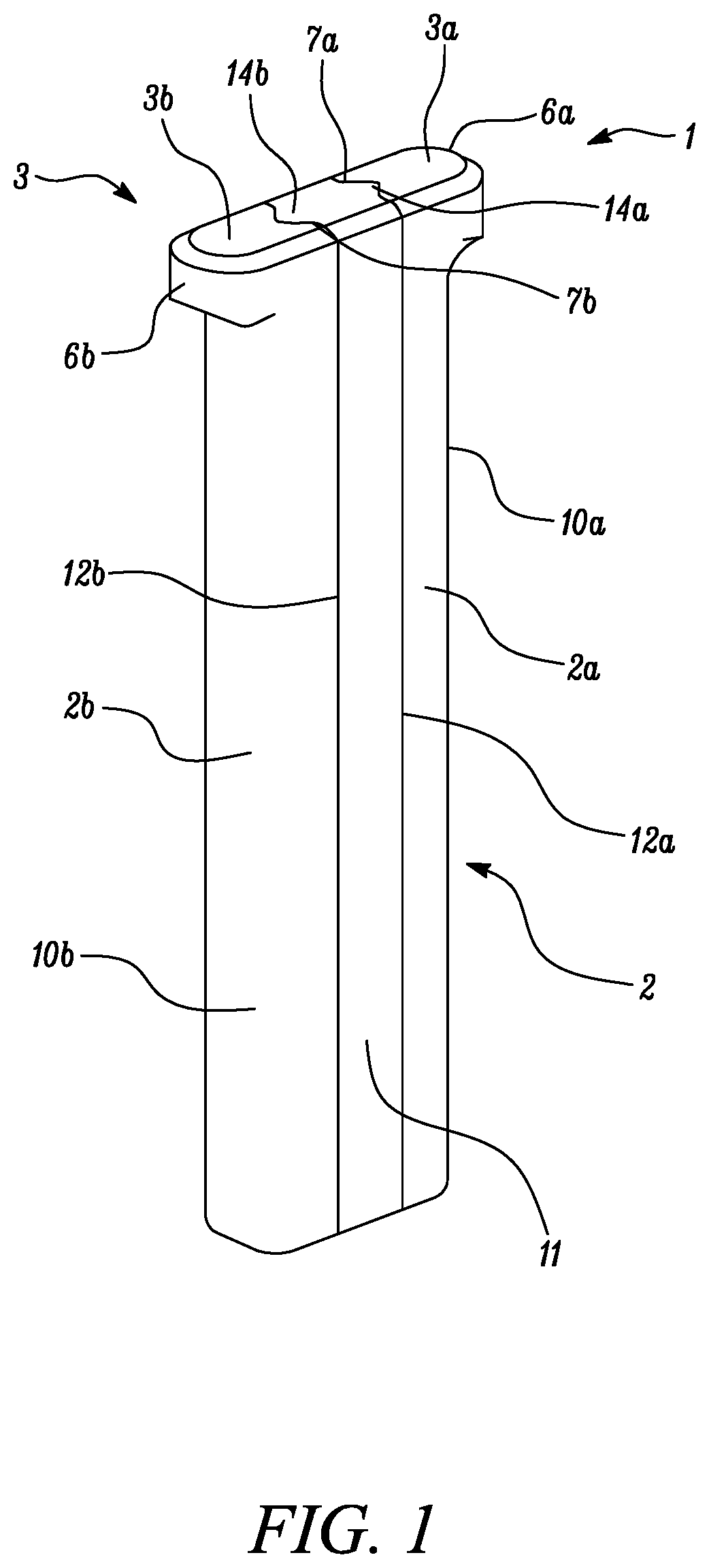
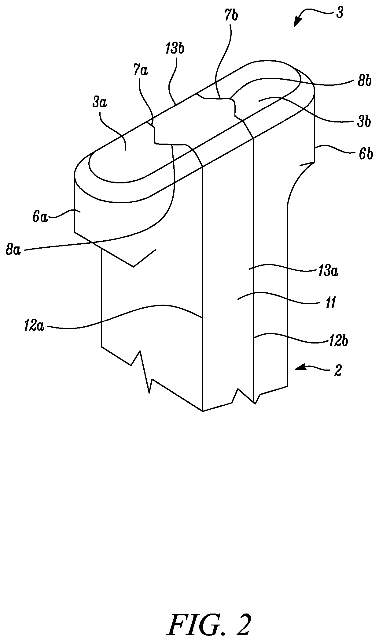
[0042]FIGS. 1 and 2 show perspective views of a gauge 1 in the inspection configuration.

[0043]The gauge comprises an elongate rod 2 and a head 3 having a transverse dimension perpendicular to the elongate axis of the rod 2. The head 3 has a larger transverse dimension than the rod 2.

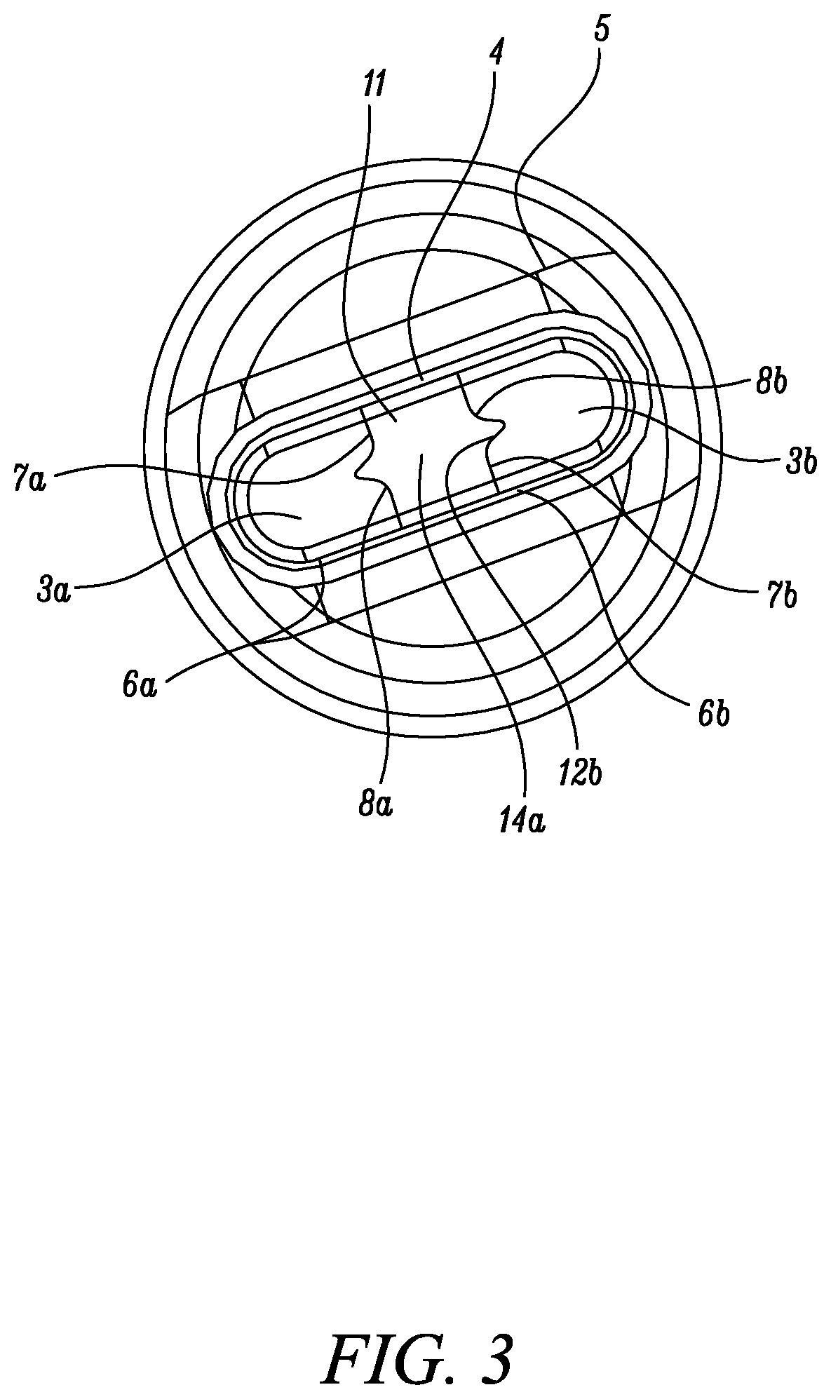
[0044]The gauge 1 has an inspection configuration (shown in FIGS. 1 to 3 & 5) wherein the transverse dimension (and the perimeter) of the head 3 is greater than in an insertion configuration shown in FIG. 4.

[0045]This allows insertion of the gauge 1 into a bore 4 of a gas turbine component 5 (e.g. a low pressure nozzle guide vane vent and oil scavenge pipe) in its reduced size insertion configuration (as shown in FIG. 4) so that the head 3 can pass any restriction 15 within the bore 4. Once the restriction ha...


PUM


Abstract

A gauge comprising an elongate rod and a head. The rod has an elongate axis. The head has a transverse dimension perpendicular to the elongate axis of the rod. The gauge has an insertion configuration and an inspection configuration, wherein the transverse dimension of the head is greater in the inspection configuration than in the insertion configuration. The head comprises two head portions each with a longitudinally-extending outer surface and a longitudinally-extending inner surface and, in the insertion configuration, the inner surfaces of the head portions are at least partly in abutment with each other. The gauge can be used in a method of measuring an internal dimension of a bore within a component.

Description

CROSS-REFERENCE TO RELATED APPLICATIONS[0001]This specification is based on and claims the benefit of United Kingdom patent application GB 1915424.4, filed on Oct. 24th, 2019, the entire contents of which is incorporated herein in its entirety by reference.BACKGROUNDTechnical Field[0002]The present disclosure relates to a gauge and in particular to a gauge for assessing the internal dimensions of a component. The present disclosure also relates to a method of using the gauge to assess the internal dimensions of a component, e.g. a gas turbine engine component.Description of the Related Art[0003]There is often the need to measure the internal dimensions of a component e.g. to ensure that the dimensions are within acceptable tolerances. This quality control is essential to ensure optimum and / or safe performance of the component.[0004]Such measurement of internal dimensions can be problematic where the component has a complex geometry rendering the internal dimension inaccessible. In p...

Claims


Application Information

Patent Timeline
IPC IPC(8): G01B3/46
CPCG01B3/46F02C7/00G01B3/50
Inventor BURTON, JONATHAN L.HOOK, DAVID
Owner ROLLS ROYCE PLC
Why Eureka
Try Eureka