Projection device

Active Publication Date: 2021-04-29
DELTA ELECTRONICS INC
View PDF0 Cites 4 Cited by
  • Summary
  • Abstract
  • Description
  • Claims
  • Application Information

AI Technical Summary

Benefits of technology

[0005]The present disclosure is to provide a projection device having a heat dissipation module for an off-state light. By disposing at least one reflective component and a heat dissipation module spatially corresponding to a first light-emitting side and a second light-emitting side of the prism set, respectively, it solves the problem that it is d

Problems solved by technology

However, when the projection device is actually used, it does not continuously provide an on-state light to produce a projected bright picture.
Since the optical mechanism of the conventional projection device adopts a closed casing design, the heat energy is not easy to be dissipated from the inside.
Consequently, the accumulated heat may cause the temperature of the internal critical optical components to be too high, thereby damaging or malfunctioning.
Due to the limitation of occupied space relative to other components, the thickness of the barrier sheet is thin, so that the thermal resistance for heat diffusion is high, and the heat dissipation effect is not good.
Moreover, due

Method used


Image

  • Projection device
  • Projection device
  • Projection device

Examples


Embodiment Construction

[0044]The present disclosure will now be described more specifically with reference to the following embodiments. It is to be noted that the following descriptions of preferred embodiments of this disclosure are presented herein for purpose of illustration and description only. It is not intended to be exhaustive or to be limited to the precise form disclosed.

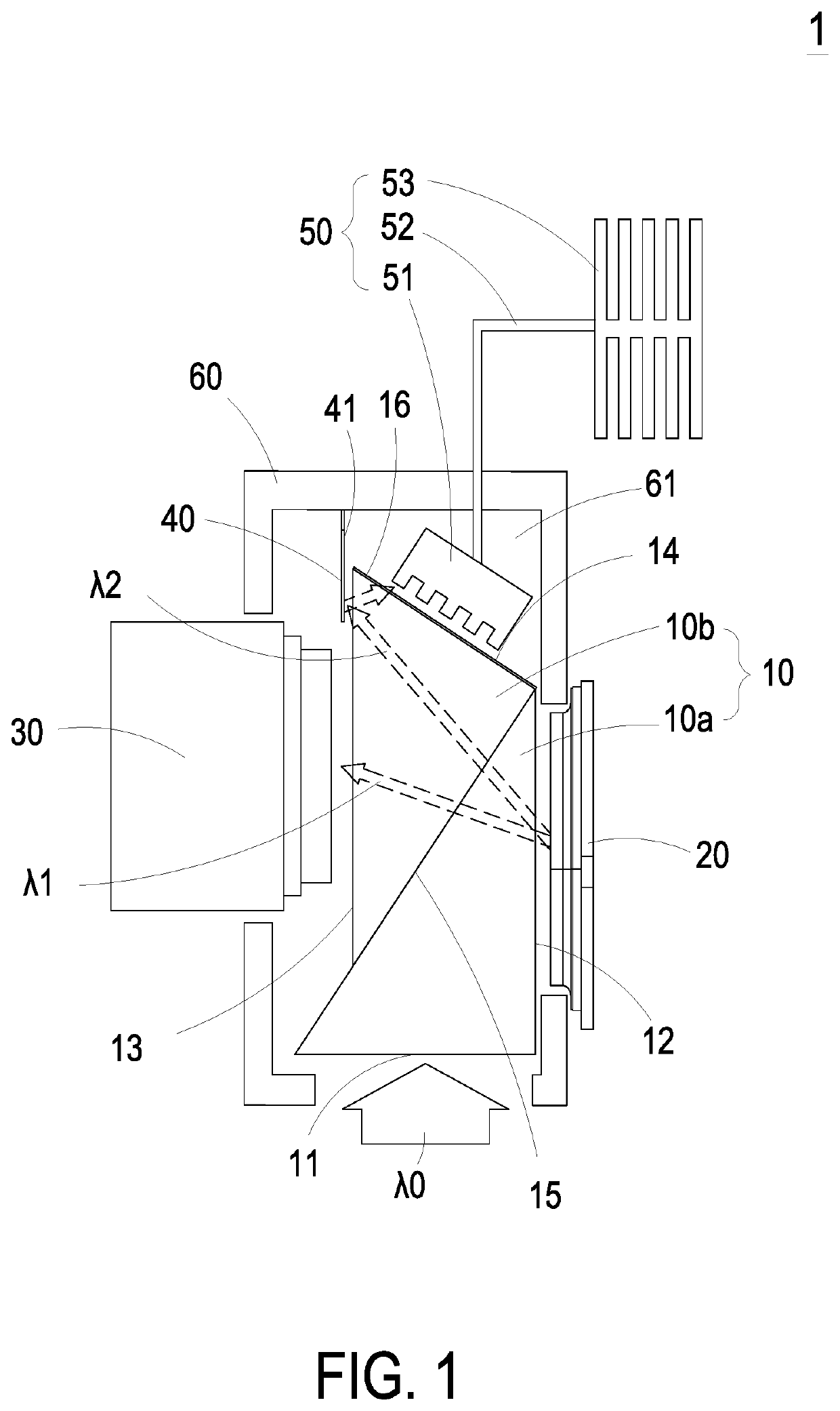
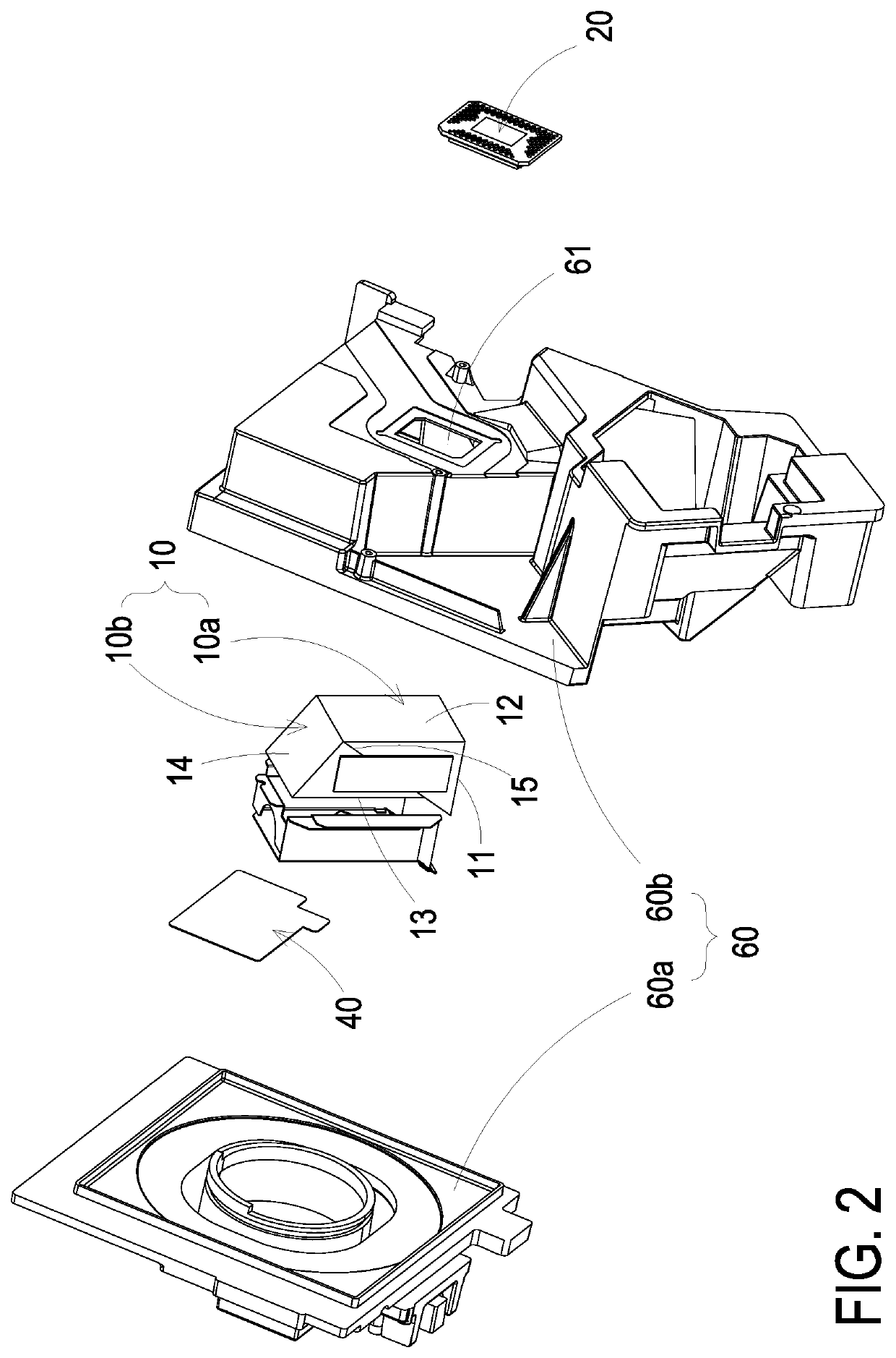
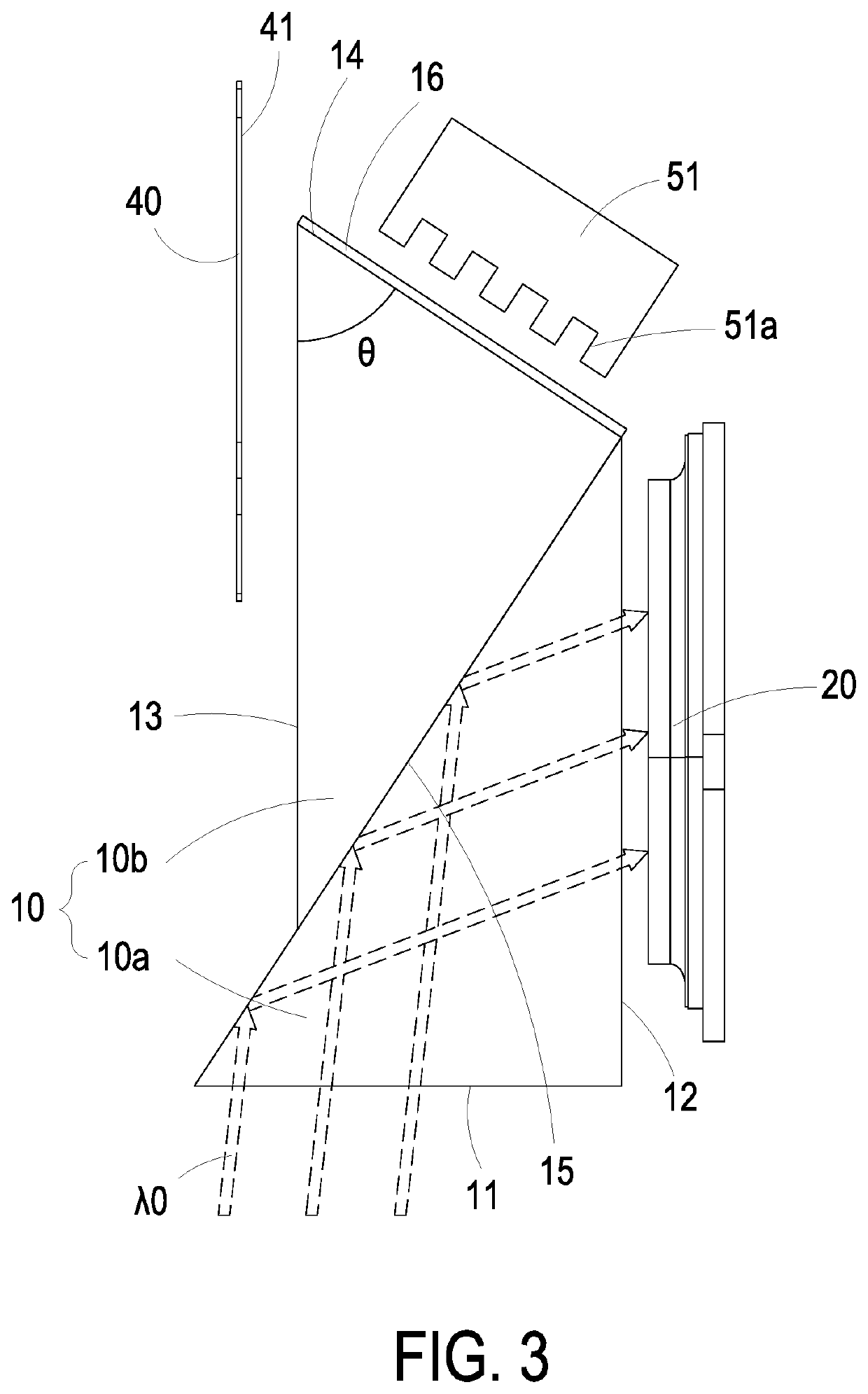
[0045]FIG. 1 is a structural view illustrating a projection device according to a first embodiment of the present disclosure. FIG. 2 is a partial structural view illustrating the projection device according to the first embodiment of the present disclosure. FIG. 3 is a light path diagram of an incident light of the projection device according to the first embodiment of the present disclosure. FIG. 4 is a light path diagram of an on-state light of the projection device according to the first embodiment of the present disclosure. FIG. 5 is a light path diagram of an off-state light of the projection device according to the first ...


PUM


Abstract

A projection device includes a prism set, a digital micro-mirror device, a reflective component and a heat dissipation module. The prism set includes a light-incident side and a mirror-corresponding side opposite to each other, and includes a first light-emitting side and a second light-emitting side adjacent to each other. The digital micro-mirror device spatially corresponds to the mirror-corresponding side. An incident light is transmitted through the light-incident side to irradiate the digital micro-mirror device. When the digital micro-mirror device generates an on-state light, the on-state light is outputted through the first light-emitting side. When the digital micro-mirror device generates an off-state light, the off-state light is transmitted toward the reflective component and outputted through the second light-emitting side. The heat dissipation module spatially corresponding to the second light-emitting side is configured to absorb and convert the off-state light for heat dissipation.

Description

FIELD OF THE INVENTION[0001]The present disclosure relates to a projection device, and more particularly to a projection device having a heat dissipation module for an off-state light.BACKGROUND OF THE INVENTION[0002]In response to market demand, the current projection device tends to pursue an increase in brightness continuously. It means that power supplied to the projection device is increased and accompanied by heat generation. However, when the projection device is actually used, it does not continuously provide an on-state light to produce a projected bright picture. When the projection device is operated to provide an off-state light, the projected bright picture disappears to present a dark picture, and most of the light energy of the projection device is remained inside the optical mechanism. Since the optical mechanism of the conventional projection device adopts a closed casing design, the heat energy is not easy to be dissipated from the inside. Consequently, the accumul...

Claims


Application Information

Patent Timeline
IPC IPC(8): G03B21/16G03B21/20G02B26/08
CPCG03B21/16G03B21/2033G02B26/0833G03B21/2066G03B21/008G03B21/145H04N9/3111H04N9/3144G02B26/0883H04N9/3108
Inventor TSAI, YI-TING
Owner DELTA ELECTRONICS INC
Why Eureka
Try Eureka