
Vehicle sensor unit

a technology for vehicle sensors and sensors, applied in the direction of vehicle cleaning, instruments, measurement devices, etc., can solve the problems of normal detection operation of infrared sensors deterioration, and achieve the effect of enhancing liquid repellency, preventing foreign objects, and effectively preventing projection portions

Pending Publication Date: 2021-05-06
TOYODA GOSEI CO LTD
View PDF8 Cites 1 Cited by
  • Summary
  • Abstract
  • Description
  • Claims
  • Application Information

AI Technical Summary

Benefits of technology

The present invention is a vehicle sensor unit that prevents foreign matters from adhering to the surface of its cover while maintaining the normal detection operation of its infrared sensor. The invention achieves this by using multiple fine projection portions on the surface of the cover to enhance its liquid repellency, preventing foreign matters such as rainwater, snow, and dirt from adhering to the cover. The projection portions are positioned close enough to the infrared ray's path to prevent its transmission and reception. Even if dirt is fixed to the cover, a washing liquid can be sprayed onto it to quickly wash off the dirt. The washing liquid can prevent a liquid film from being formed in the gap between the projection portions, ensuring the detection operation of the infrared sensor is not hindered. Overall, the invention prevents foreign matters from affecting the infrared sensor's detection while maintaining its normal operation.

Problems solved by technology

In a case where an infrared sensor is used instead of the radio wave radar in the in-vehicle radar device described above, when the infrared sensor transmits and receives an infrared ray, the infrared ray is scattered by the plurality of recesses formed on the outer surface of the radome, so that a normal detection operation of the infrared sensor may be deteriorated.

Method used


Image

  • Vehicle sensor unit
  • Vehicle sensor unit
  • Vehicle sensor unit

Examples


Embodiment Construction

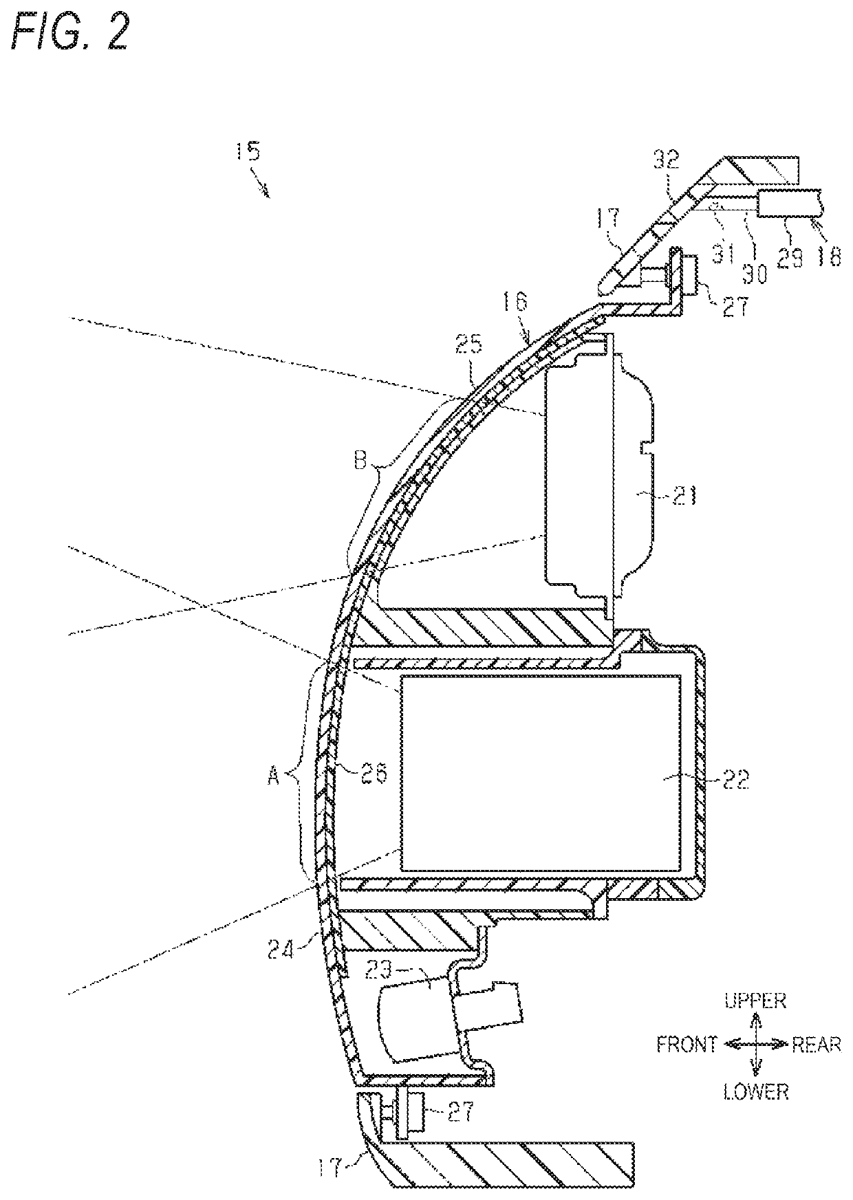
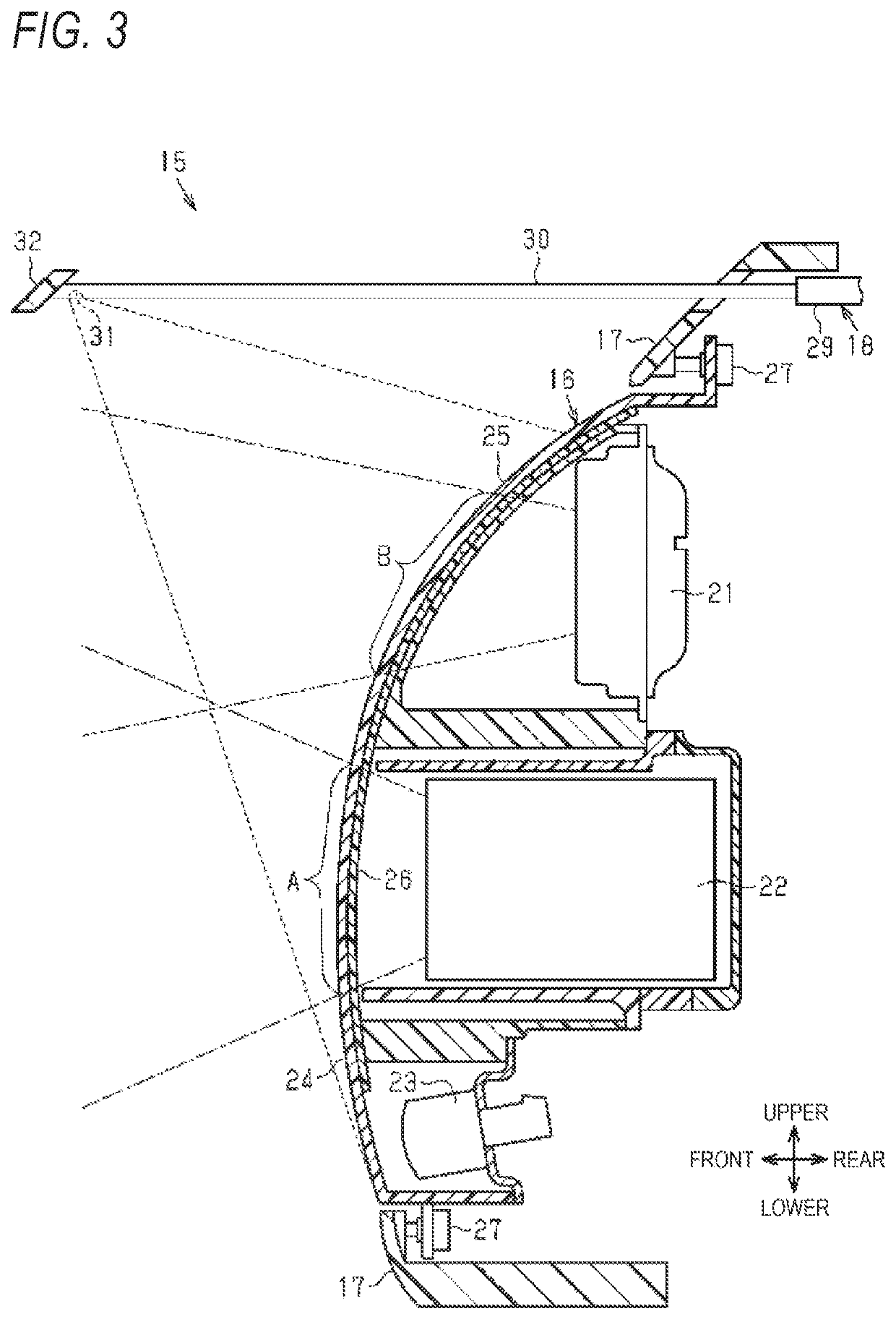
[0018]Hereinafter, a vehicle sensor unit according to an embodiment will be described with reference to the drawings.

[0019]In the following description, a forward direction of a vehicle is described as a front direction and a reverse direction is described as a rear direction. Further, an upper-lower direction means an upper-lower direction of the vehicle, and a left-right direction is a width direction of the vehicle (vehicle width direction) and is the same as a left-right direction of the vehicle when the vehicle is moving forward.

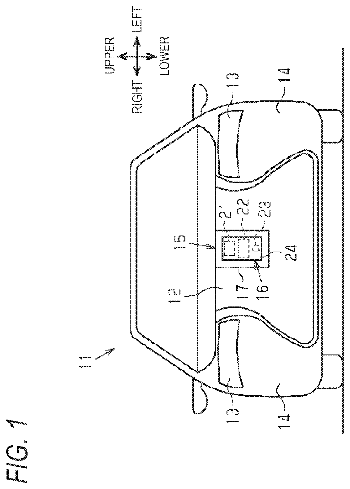
[0020]As shown in FIG. 1, a radiator grill 12, a pair of headlamps 13, and a pair of bumper-integrated fenders 14 are attached, as vehicle exterior components, to a front end portion of a vehicle body of a vehicle 11. The two headlamps 13 are respectively arranged on left and right sides of the radiator grill 12 and the two bumper-integrated fenders 14 are respectively arranged on the left and right sides of the radiator grill 12. The radiator grill 12 ...


PUM

PropertyMeasurementUnit
frequencyaaaaaaaaaa
wavelengthaaaaaaaaaa

Abstract

A vehicle sensor unit includes an infrared sensor configured to transmit an infrared ray to an outside of the vehicle, and receive an infrared ray reflected by a detection target object outside the vehicle, and a cover which is located in front of the infrared sensor in a transmission direction of the infrared ray to cover the infrared sensor and through which the infrared ray passes. A plurality of fine projection portions are formed on a surface of the cover on an opposite side of a surface on an infrared sensor side, at least in a region through which the infrared ray passes, and an interval between the projection portions that are adjacent to each other is equal to or smaller than a wavelength of the infrared ray.

Description

CROSS-REFERENCE TO RELATED APPLICATIONS[0001]The present application claims the benefit of priority of Japanese Patent Application No. 2019-201469, filed on Nov. 6, 2019, the content of which is incorporated herein by reference.TECHNICAL FIELD[0002]The present invention relates to a vehicle sensor unit provided at an outer end portion of a vehicle and having a function of detecting a situation around the vehicle.BACKGROUND ART[0003]In the related art, as a vehicle sensor unit of this type, there is known an in-vehicle radar device as disclosed in JP-B-3659951, for example. Such an in-vehicle radar device includes a radio wave radar disposed at an outer end portion on a front end portion or the like of a vehicle, and a plate-shaped radome that is made of a radio wave-transmitting member and is disposed in front of the radio wave radar. The radio wave radar detects a detection target object by transmitting a radio wave to an outside of the vehicle and receiving a radio wave reflected ...

Claims


Application Information

Patent Timeline
Patent Type & Authority Applications(United States)
IPC IPC(8): G01S17/931G01S17/06G01S17/58G01S13/06G01S13/58G01S13/931B60S1/46
CPCG01S17/931G01S17/06G01S17/58B60S1/46G01S13/58G01S13/931G01S13/06B60S1/528B60S1/56G01S7/4813G01S2007/4977G01S7/4043G01S7/027G01S2013/93271
Inventor TANAKA, MITSUEICHIKAWA, TADAOKIMISAWA, AKIHIRO
Owner TOYODA GOSEI CO LTD
Learn More