
Stereo endoscope

a technology of endoscope and endoscope, which is applied in the field of stereo endoscope, can solve problems such as increasing challenges, and achieve the effects of improving ratio, simplifying image data processing, and increasing outlay

Pending Publication Date: 2021-05-13
KARL STORZ GMBH & CO KG
View PDF4 Cites 0 Cited by
  • Summary
  • Abstract
  • Description
  • Claims
  • Application Information

AI Technical Summary

Benefits of technology

The patent text describes a way to save space when installing image sensors. By arranging the sensors next to each other, their use of space is maximized. Additionally, chamfering or beveling the edge of the prism near the outer surface of the shaft can further reduce the amount of space needed. This results in a more compact structure. The technical effect is a more efficient use of space and a more compact structure for image sensor arrangements.

Problems solved by technology

The arrangement of two image sensors in a distal end region of an endoscope, in particular, represents a technical challenge.
This challenge increases with increasing miniaturization.

Method used


Image

  • Stereo endoscope
  • Stereo endoscope
  • Stereo endoscope

Examples


Embodiment Construction

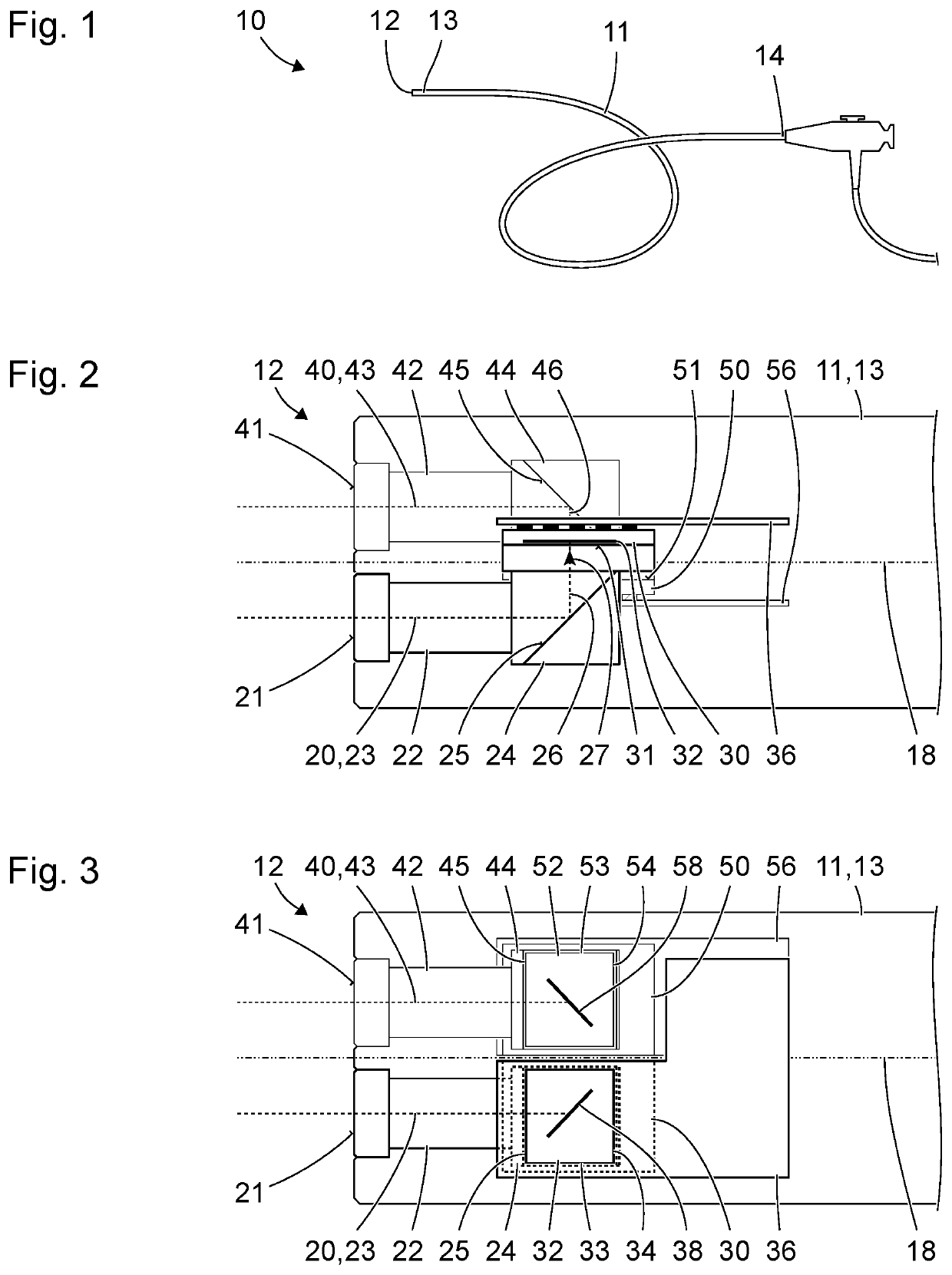
[0083]FIG. 1 shows a schematic illustration of a stereo endoscope 10 comprising a shaft 11. The shaft 11 has a distal end 12, a distal end region 13 forming the distal end 12, and a proximal end 14. The shaft 11 is flexible between the proximal end 14 and the distal end region 13, i.e., it is non-destructively elastically or plastically deformable within structurally defined limits. The distal end region of 13 of the shaft 11 is rigid and straight. As an alternative and deviating from the illustration in FIG. 1, the shaft 11 can have a rigid and curved or rigid and straight embodiment.

[0084]FIG. 2 shows an enlarged schematic illustration of the distal end region 13 of the shaft 11 of the stereo endoscope of FIG. 1. In FIG. 2, the distal end region 13 of the shaft 11 is represented in transparent fashion, i.e., only indicated by contours such that devices within the shaft 11 and the end region 13 are visible.

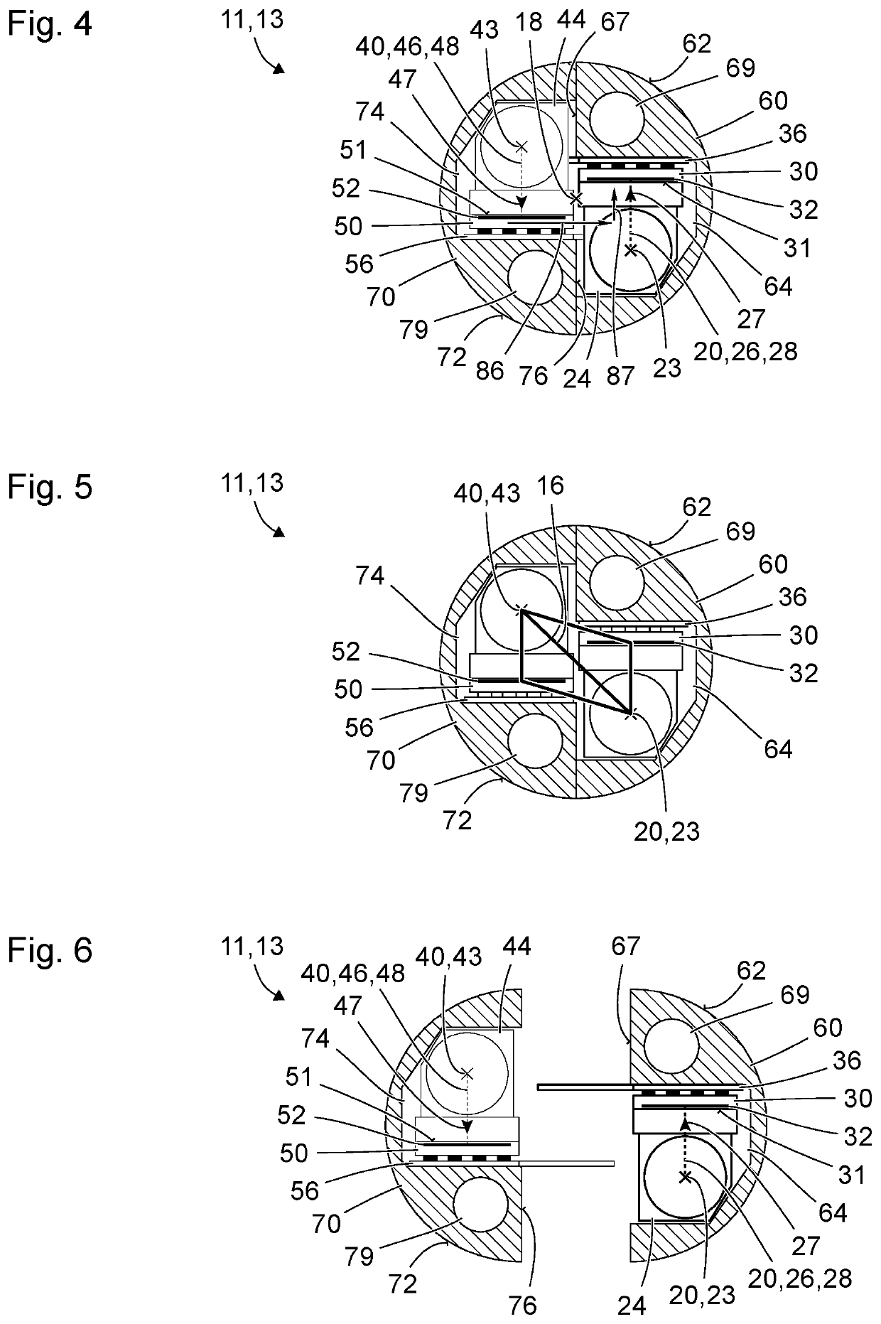
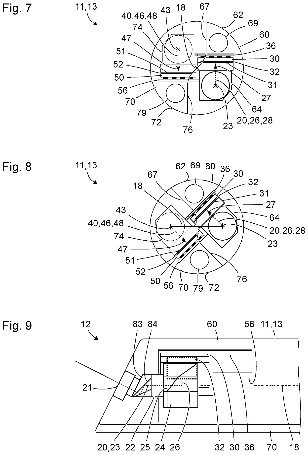
[0085]The illustrated example is a stereo endoscope which looks straight ahe...


PUM


Abstract

A stereo endoscope for capturing a first image which is provided to be observed by a first eye and a second image which is provided to be observed by a second eye, including a shaft with a distal end region, a first image sensor in the distal end region of the shaft, for capturing the first image, and a second image sensor in the distal end region of the shaft, for capturing the second image. The first image sensor and the second image sensor are arranged offset relative to one another in a direction which is parallel to at least either a light-sensitive layer of the first image sensor or a light-sensitive layer of the second image sensor and which is orthogonal to a longitudinal axis the distal end region of the shaft. The first image sensor and the second image sensor are oriented in opposite directions.

Description

TECHNICAL FIELD[0001]The present invention relates to a stereo endoscope for capturing an image which is provided to be observed by the left eye and an image which is provided to be observed by the right eye. The present invention relates, in particular, to a stereo endoscope in which the image sensors for capturing the two images are arranged in a distal end region of the stereo endoscope.BACKGROUND OF THE INVENTION[0002]In an endoscope, the image generated at the distal end by an objective can be transmitted by a relay lens system, a coherent bundle of optical fibers or in any other way to the proximal end and can be captured there by an integrated or mechanically and optically coupled camera, and a corresponding image signal can be produced. Alternatively, the image generated by the objective are captured by an image sensor arranged close to the distal end, and a corresponding image signal can be produced. This applies equally to monocular endoscopes and stereoscopic endoscopes.[...

Claims


Application Information

Patent Timeline
Patent Type & Authority Applications(United States)
IPC IPC(8): A61B1/00A61B1/05
CPCA61B1/00193A61B1/05A61B1/00165A61B1/00009G02B23/2415G02B23/2423
Inventor FORSTER, JONAS
Owner KARL STORZ GMBH & CO KG
Learn More