Weightlifting apparatus

a technology for lifting apparatuses and weights, applied in the field of lifting apparatuses, can solve the problems of weightlifters incurring additional costs, and achieve the effects of preventing corrosion, ensuring grip on the apparatus, and favorable grip performan

Inactive Publication Date: 2021-05-13
PRO FITNESS INNOVATIONS LLC
View PDF0 Cites 3 Cited by
  • Summary
  • Abstract
  • Description
  • Claims
  • Application Information

AI Technical Summary

Benefits of technology

[0008]Optionally, each of the at least one pair of spaced-apart handles is coupled to a top portion of the frame at a first end and each of the at least one pair of spaced-apart handles is coupled to a bottom portion of the frame at a second end. This configuration of the apparatus provides for stability and durability. Similarly, in one embodiment of the apparatus of the present invention, the elongate shaft is coupled at its proximal end to the frame by a welded connection.
[0009]Weight plates that are commercially available to weightlifters generally include a hole penetrating the center of the plate so as to be aligned with the center of mass of the plate. The hole is generally circular in shape. As a result, a preferred embodiment of the apparatus of the present invention includes an elongate shaft having a circular cross-section sized to receive standard weight plates thereon. A variety of securing collars such as collars that are securable on a shaft using a set screw and collars that are securable on a shaft using elastically expandable coils can be used to secure weight plates on the shaft to prevent them from inadvertently sliding off of the shaft during use.
[0010]Embodiments of the apparatus may be of a material that can be coated using paint or other materials for preventing corrosion and for aesthetic appearance. In one embodiment of the apparatus of the present invention, the at one pair of spaced-apart handles can be coated or fitted with at least one pair of sleeves sized to be received onto the handles and having favorable grip performance to enable the weight lifter to maintain a secure grip on the apparatus. Alternately, an embodiment of the apparatus of the present invention may include at least one pair of spaced-apart handles that are knurled to provide a favorable gripping surface.

Problems solved by technology

These dumbbells cause the weightlifter to incur additional costs.

Method used


Image

  • Weightlifting apparatus
  • Weightlifting apparatus

Examples


Embodiment Construction

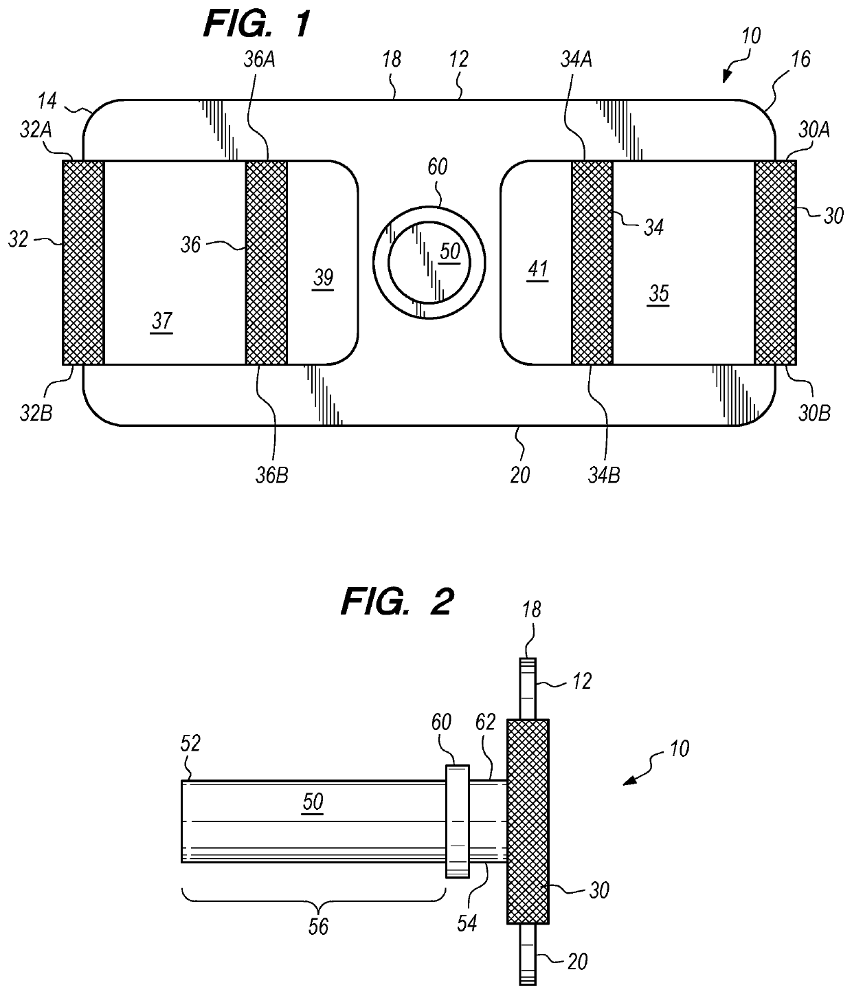
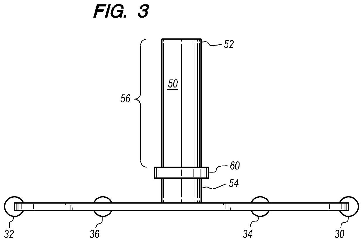
[0014]FIG. 1 is a frontal elevation view of an embodiment of the apparatus 10 of the present invention. The embodiment of the apparatus 10 of FIG. 1 comprises a frame 12 having a first end 14, a second end 16, a top side 18 and a bottom side 20. The frame 12 of the apparatus 10 further includes a first pair of spaced-apart handles 30 and 32, and a second pair of spaced apart handles 34 and 36. The apparatus 10 further includes a shaft 50 coupled at a connection 60 to the frame 12 intermediate the first pair of spaced-apart handles 30 and 32 and intermediate the second pair of spaced-apart handles 34 and 36. The first pair of spaced-apart handles 30 and 32 and intermediate the second pair of spaced-apart handles 34 and 36. The rightmost handle 30 of the first pair of spaced-apart handles 30 and 32 is coupled to the frame at an upper end 30A and a lower end 30B. The leftmost handle 32 of the first pair of spaced-apart handles 30 and 32 is coupled to the frame at an upper end 32A and a...


PUM


Abstract

A weightlifting apparatus that includes a frame having at least one pair of spaced-apart handles thereon and an elongate shaft having a distal end and a proximal end coupled to the frame intermediate each of the at least one pair of spaced-apart handles. The shaft may be circular in cross-section and sized to receive a standard weight plate thereon. The weightlifting apparatus enables a weightlifter to enjoy additional benefits from standard weight plates that are normally used with barbells and to perform additional exercises with the hands in positions that cannot be achieved using barbells so as to exercise different muscle groups.

Description

BACKGROUNDField of the Invention[0001]The present invention relates to a weightlifting apparatus that can receive and secure one or more weight plates and that includes handles to enable the user to lift and manipulate the one or more weight plates secured thereto.Background of the Related Art[0002]Weight plates are very common devices used by weightlifters. Weight plates are generally used with barbells that are elongated rods having a shaft on each end for receiving and securing weight plates to the barbell. The weight plates each include a centrally located hole at the center of the weight plate sized for being received onto the shaft at the end of the barbell. A collar, such as a spring coil collar or a collar with a threaded bolt, can be secured onto the shaft intermediate the weight plates and the end of the barbell shaft to secure the weight plates onto the shaft. The barbell, with the weight plates secured thereto, can then be used in weightlifting exercises such as bench pr...

Claims


Application Information

Patent Timeline
Patent Type & Authority Applications(United States)
IPC IPC(8): A63B21/072A63B21/00
CPCA63B21/0728A63B21/4035A63B21/072A63B21/0724
Inventor PACINI, JOHNNORRIS, JOSHUA GENE
Owner PRO FITNESS INNOVATIONS LLC
Why Eureka
Try Eureka