
Traveling body system

a body system and travel technology, applied in the field of travel body systems, can solve problems such as the possibility of electric shock to workers, and achieve the effect of improving the safety of workers

Pending Publication Date: 2021-05-13
MURATA MASCH LTD +1
View PDF0 Cites 2 Cited by
  • Summary
  • Abstract
  • Description
  • Claims
  • Application Information

AI Technical Summary

Benefits of technology

The present invention provides safety improvements for workers in traveling body systems of tire power supply systems. The system uses electrical insulators to cover the metal rails, reducing the risk of electric shock for workers. Additionally, the second electrical insulator and conductor can be integrally formed, improving manufacturing, carrying, and attaching efficiency. The system also uses differential transmission for high frequency power supply, minimizing risks to existing electrical equipment. Overall, the invention improves safety for workers in tire power supply systems.

Problems solved by technology

Therefore, if a worker carelessly touches the rail, the worker may receive an electric shock.

Method used


Image

  • Traveling body system
  • Traveling body system
  • Traveling body system

Examples


Embodiment Construction

1. First Preferred Embodiment

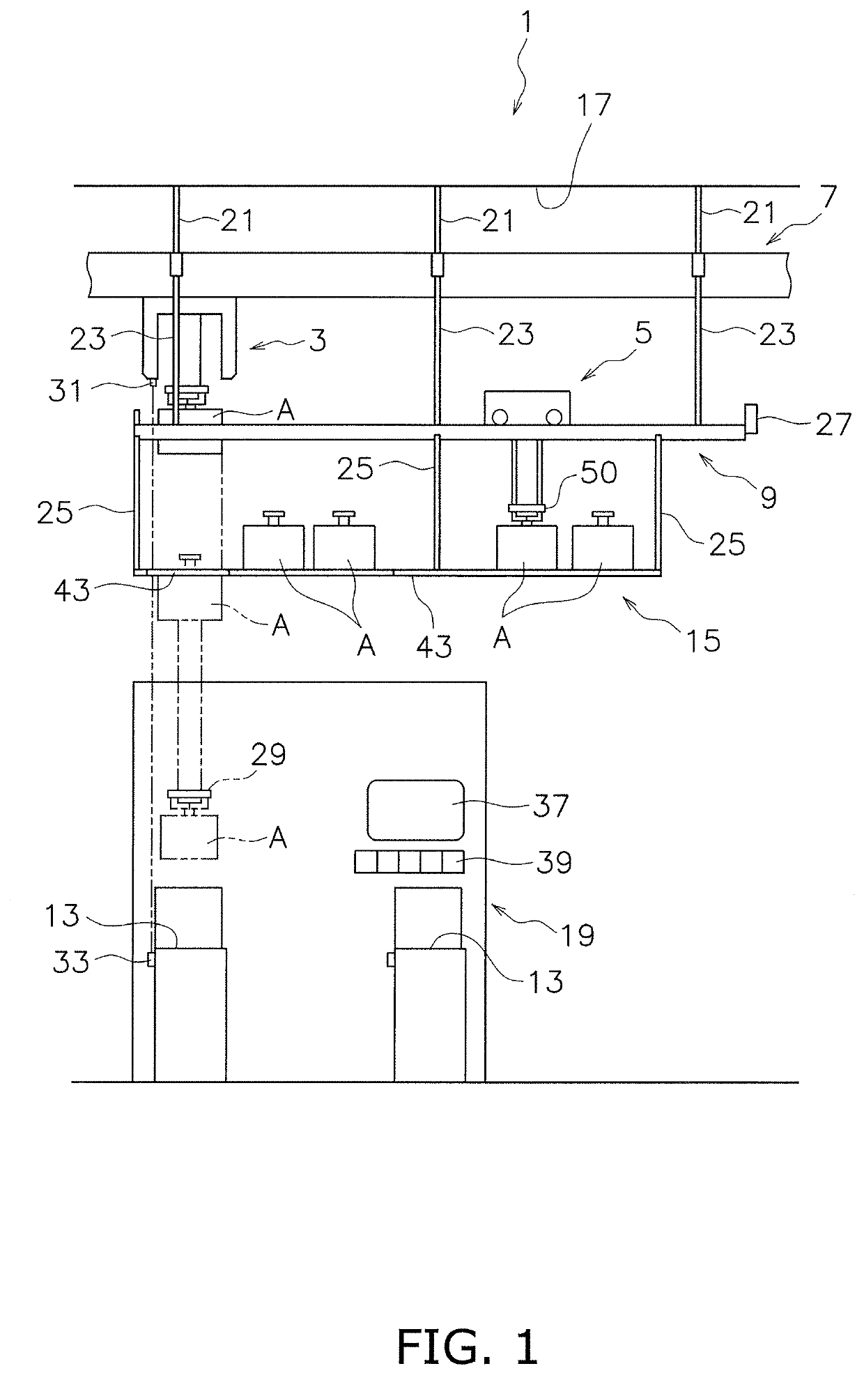
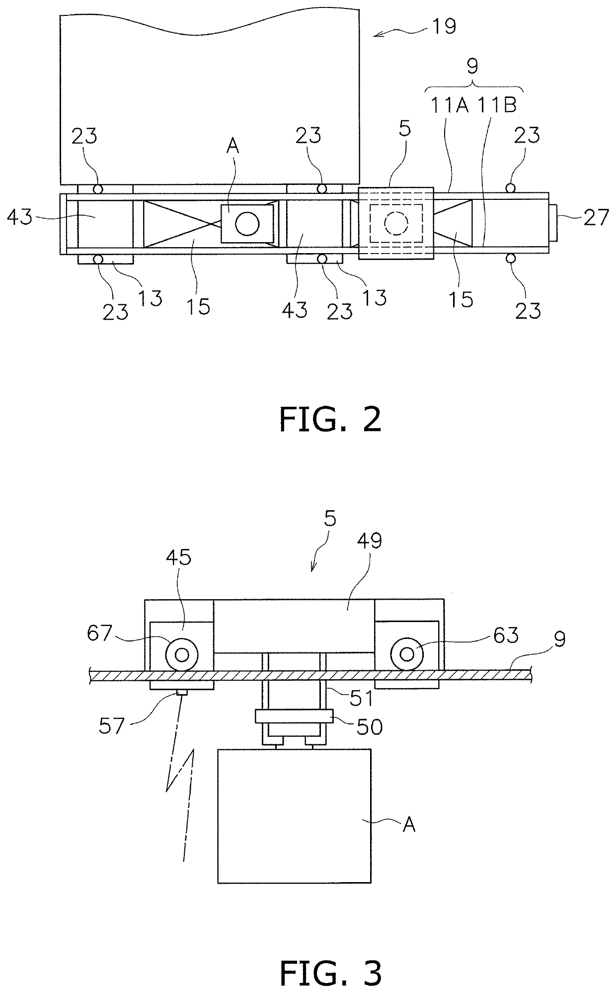
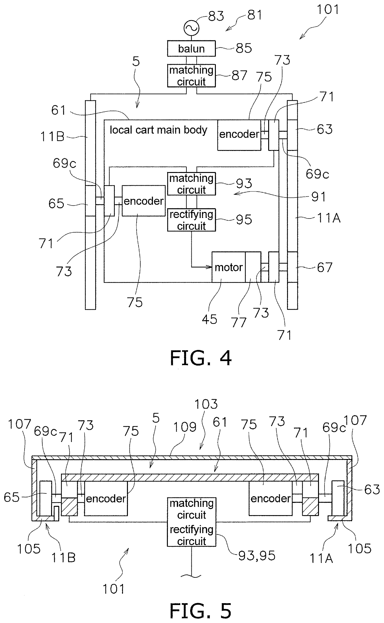
[0047]A transport system 1 of a first preferred embodiment of the present invention is described with reference to FIGS. 1 to 3. FIG. 1 is a side view of a main portion of the transport system 1 of the first preferred embodiment. FIG. 2 is a plan view of a main portion of the transport system 1. FIG. 3 is a side view of a local cart 5.

[0048]The transport system 1 includes a ceiling traveling vehicle 3. The ceiling traveling vehicle 3 performs interbay transportation and intrabay transportation in a semiconductor factory, for example.

[0049]The transport system 1 includes the local cart 5. The local cart 5 loads and unloads an article A such as an FOUP with respect to each processor 19, or loads and unloads articles A with respect to a plurality of neighboring processors 19.

[0050]The transport system 1 includes a first track 7. The first track 7 is a track of the ceiling traveling vehicle 3 and includes a metal rail and a conductor.

[0051]The transport syst...


PUM


Abstract

In a local cart traveling system, a frame track includes first and second metal rails each with an L-shaped cross section and facing each other. A local cart is within the frame track, and includes a first electricity receiving tire and a second electricity receiving tire to travel on horizontal travel surfaces of the rails. A voltage supplier supplies an AC voltage to the travel surfaces, so that the first metal rail and a first electricity receiving tire define a first capacitor and the second metal rail and the second electricity receiving tire define a second capacitor. The local cart includes a power receiver to receive AC power, and a travel motor that receives power after the AC power is rectified. The frame track includes a connecting plate as an electrical insulator covering portions of the surfaces of vertical walls of the first metal rail and the second metal rail.

Description

BACKGROUND OF THE INVENTION1. Field of the Invention[0001]The present invention relates to a traveling body system. In particular, the present invention relates to a traveling body system in which AC power is taken out from a capacitor between a metal rail and a wheel so as to drive a travel motor.2. Description of the Related Art[0002]As a method for supplying power to a vehicle, so-called tire power supply is known. The tire power supply is a wireless power transfer technique using capacitive coupling between a rail and a metal body inside the tire.[0003]The following technique is known as the tire power supply. Two conductors are placed on the floor surface and are supplied with AC power. The two conductors and steel belts inside the two tires of the vehicle define capacitors. AC power is taken out from two electrodes that are adjacent to the tires and are capacitively coupled to the steel belts. The taken-out AC power is rectified and stored in a battery (see, for example, Japan...

Claims


Application Information

Patent Timeline
IPC IPC(8): B60L9/12B60M7/00B60L5/38H01L21/677
CPCB60L9/12B60M7/00H01L21/67733H01L21/67724B60L5/38H01L21/67706H01L21/6773B60L2200/36B60L9/00B60L2200/26B61B3/02
Inventor MIZUTANI, MINORUISHIKAWA, KAZUHIROHAYAKAWA, MASAFUMIOHIRA, TAKASHISAKAI, NAOKIKUNIYOSHI, HIROKITERAMOTO, MAKOTO
Owner MURATA MASCH LTD
Learn More