Method and apparatus for monitoring particles

a technology of particle concentration and monitoring method, which is applied in the direction of chemistry apparatus and processes, instruments, suspensions and porous materials, etc., can solve the problems of non-expensive and reliable measurement of particle concentration, and achieve the effects of reducing the loss of charged particles in the charger, increasing the penetration of pch through the charger, and decreasing the residence tim

Active Publication Date: 2021-05-13
PEGASOR OY
View PDF9 Cites 2 Cited by
  • Summary
  • Abstract
  • Description
  • Claims
  • Application Information

AI Technical Summary

Benefits of technology

[0029]As seen in equation 2, the direct effect of the sample flow rate cancels out from the instrument response. This makes the response relatively independent of the flow rate and this does not happen if for any particle size all the particles are collected.
[0030]Although the direct flow rate effect is canceled, the product Pchn2 is still in principle dependent on the flow rate. The charged particle losses in the charger decrease with decreasing residence time in the electric field. Therefore, the penetration Pch through the charger is increased with increasing sample flow rate Qs. The penetration as a function of flow rate is usually not a well-defined quantity, but it can be approximated by modeling the charger as a turbulent electrostatic precipitator (ESP). This would lead to flow dependence of the form of

Problems solved by technology

The problem is thus non-expensive and reliable measurement of particle concentration, especially the measurement of ultrafine (less than 0.1 μm in diameter) particle concentration, in a fluctuating flow.

Method used


Image

  • Method and apparatus for monitoring particles
  • Method and apparatus for monitoring particles
  • Method and apparatus for monitoring particles

Examples


Embodiment Construction

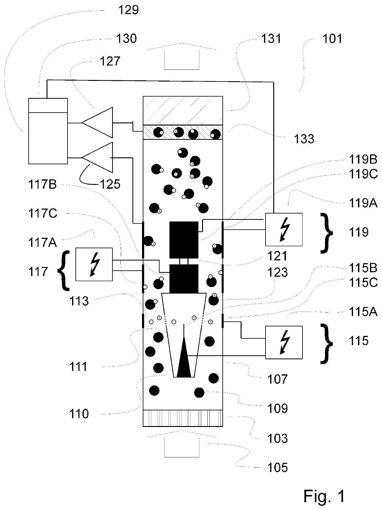
lass="d_n">[0056]The invented method comprises measuring or monitoring the content of particulate matter in a flowing gas stream. In the method, electrical particle charging is used to charge at least some of the particles in sample flow taken into the measurement apparatus. The electrical current carried by at least some of the charged particles is measured, and thus that is the response of the method. Typical feature of the method is that it can measure the content of particulate matter within + / −10% accuracy when the volumetric flow through the measuring or monitoring apparatus which is measuring or monitoring particulate content in the flowing gas stream has a dynamic range of 10, i.e. with nominal flow, Qsample or Qs, is 1, the flow range is 0.3-3. The term “accuracy” has here the meaning that when the particle concentration is measured with a certain volumetric flow inside the mentioned dynamic range, the same concentration in the sample flow is measured within + / −10% value fr...


PUM

PropertyMeasurementUnit
diameteraaaaaaaaaa
diameteraaaaaaaaaa
particle diameteraaaaaaaaaa

Abstract

The invention relates to a method and an apparatus for measuring particle concentrations in an aerosol. The apparatus comprises means (103) for driving flow (105) into apparatus (101), means (115) for electrically charging particles (109) to become electrically charged particles (123) by ions (113) produced by a charger, means (117) for removing free ions (113) which are not attached to the electrically charged particles (123), and means (119) for measuring electrical current carried by the electrically charged particles (123). The means (115) for charging the particles and the means (119) for measuring electrical current carried by the electrically charged particles (123) are dimensioned such that the means (119) for measuring electrical current carried by the electrically charged particles (123) only measures a part of a total current carried by the particles.

Description

BACKGROUNDField of Invention[0001]The invention relates to a method for measuring particle concentrations in an aerosol. The invention also relates to an apparatus implementing such method. The method and the apparatus can be used in e.g. measuring ambient air quality or indoor air quality. Apparatus is preferably a particle sensor measuring particle mass concentration or particle number concentration or particle (active) surface area concentration or combination thereof. Apparatus can also be utilized in building sensor networks.Description of the State of the Art[0002]Particles suspended in aerosols play a significant role in ambient and indoor air and in many technical processes. An important task lies in detecting the concentration of the particles by way of measurement technology. Particles in the size range of smaller than 10 micrometers diameter may be breathed in by humans and may have a detrimental effect on health. The most recent research results indicate that the usual p...

Claims


Application Information

Patent Timeline
Patent Type & Authority Applications(United States)
IPC IPC(8): G01N15/06B03C3/017B03C3/41B03C3/49
CPCG01N15/0656B03C3/017G01N2015/0046B03C3/49B03C3/41B03C3/06B03C3/12B03C3/368B03C2201/06
Inventor ROSTEDT, ANTTIKESKINEN, JORMASAUKKO, ERKKAJANKA, KAUKO
Owner PEGASOR OY
Why Eureka
Try Eureka