High frequency signal transmission cable and producing method therefor

Active Publication Date: 2021-05-20
HITACHI METALS LTD
View PDF0 Cites 0 Cited by
  • Summary
  • Abstract
  • Description
  • Claims
  • Application Information

AI Technical Summary

Benefits of technology

The present invention aims to provide a high frequency signal transmission cable that is resistant to signal attenuation and maintains good transmission properties even when bent and wired in a narrow space. The cable comprises an insulator and a crack suppressing layer that prevents cracks from occurring in the plating layer. The cable is made pliable and flexible while still maintaining its high frequency signal transmission properties. The present invention solves the problem of difficulty in wiring coaxial cables in narrow spaces while maintaining good signal transmission properties.

Problems solved by technology

In the coaxial cable with the tape member being cylindrically wrapped around while adhering tightly to the entire periphery of the insulator, when the coaxial cable is bent, a breaking and a wrinkling or a cracking in the tape member may occur, which may lead to a deterioration in high frequency signal transmission properties.
In addition, since the tape member being cylindrically wrapped around while adhering tightly to the entire periphery of the insulator is hard and difficult to bend, it may be difficult to wire the coaxial cable in a narrow space in a small size electronic device.
When such a coaxial cable is bent and wired by force, there is a possibility of the high frequency signal transmission properties deteriorating due to the insulator adhering tightly to and being subjected to a compression or the like by the tape member that is difficult to bend.

Method used


Image

  • High frequency signal transmission cable and producing method therefor
  • High frequency signal transmission cable and producing method therefor
  • High frequency signal transmission cable and producing method therefor

Examples


embodiment

[0025]An embodiment of the present invention will be described below with reference to the accompanying drawings.

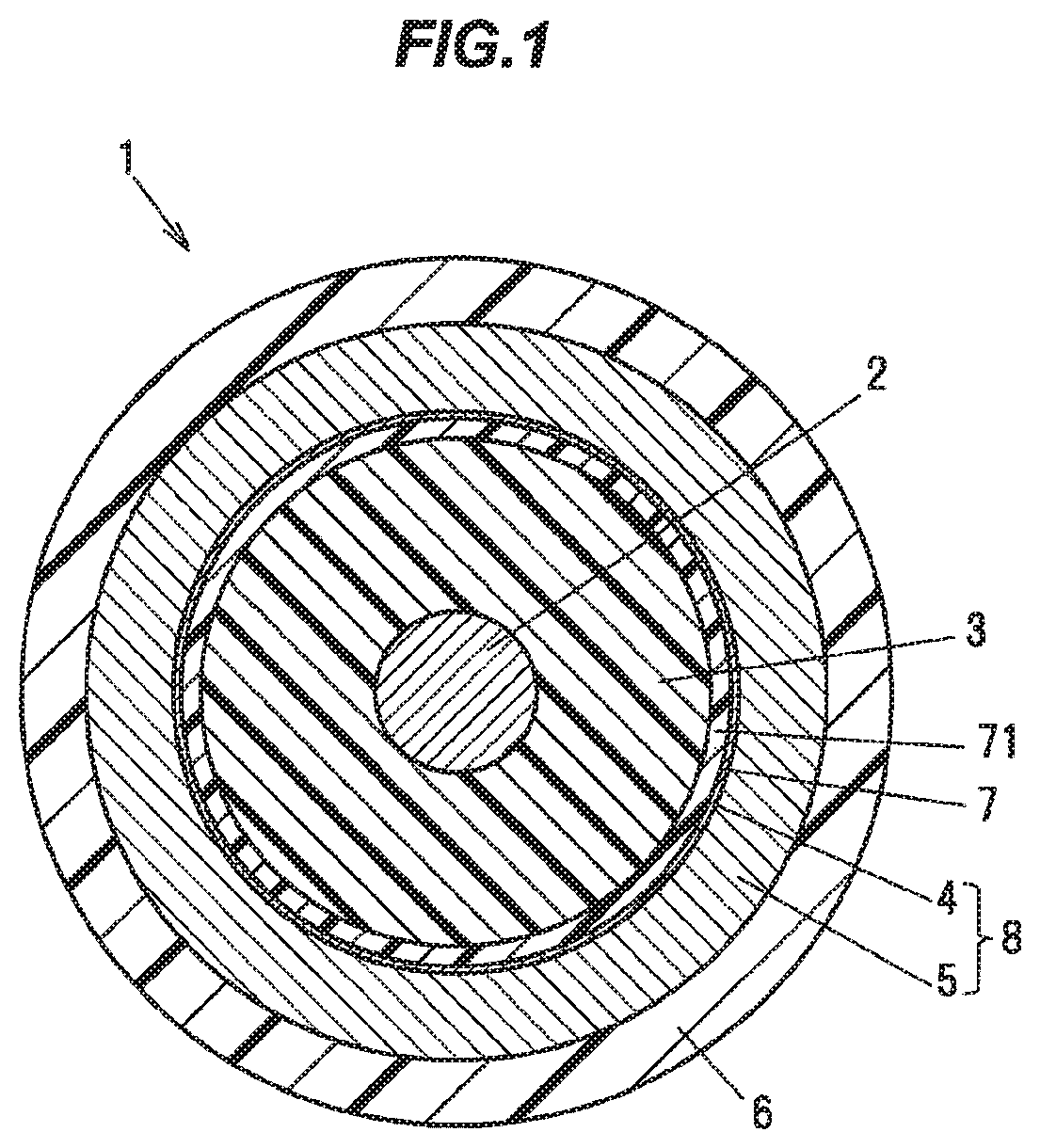
[0026]FIG. 1 is a cross-sectional view showing a cross section perpendicular to a longitudinal direction of a high frequency signal transmission cable according to the present embodiment. As shown in FIG. 1, a high frequency signal transmission cable 1 is configured to include an inner conductor 2 as a conductor arranged in a center of the cable 1, an insulator 3 that is provided over a periphery of the inner conductor 2, and a plating layer 4 that is provided over a periphery of the insulator 3, a metal shield layer 5 that is provided over a periphery of the plating layer 4, and a sheath 6 that is provided over a periphery of the metal shield layer 5. That is, the high frequency signal transmission cable 1 according to the present embodiment is configured as a coaxial cable including the inner conductor 2, the insulator 3, an outer conductor 8 (the plating layer 4 and th...


PUM

PropertyMeasurementUnit
Thicknessaaaaaaaaaa
Thicknessaaaaaaaaaa
Thicknessaaaaaaaaaa

Abstract

A high frequency signal transmission cable includes a conductor, an insulator provided over a periphery of the conductor, a plating layer provided over a periphery of the insulator, and a sheath provided over a periphery of the plating layer. A crack suppressing layer is provided between the insulator and the plating layer, in such a manner as to remain in contact with the insulator while being provided with the plating layer over an outer surface of that crack suppressing layer. The crack suppressing layer is composed of a resin film to suppress the occurrence of a cracking in the plating layer by bending while moving in a longitudinal direction of the cable relative to a bending of the insulator.

Description

CROSS-REFERENCE TO RELATED APPLICATIONS[0001]The present invention is based on Japanese Patent Application No. 2019-129378 filed on Jul. 11, 2019, the entire contents of which are incorporated herein by reference.BACKGROUND OF THE INVENTION1. Field of the Invention[0002]The present invention relates to a high frequency signal transmission cable and a producing method therefor.2. Description of the Related Art[0003]As a high frequency signal transmission cable to be wired inside imaging devices to be used in automatic operations and the like, or electronic devices such as smartphones, tablet terminals and the like, a thin diameter coaxial cable having an outer diameter of e.g. 2 mm or less is used.[0004]There is conventionally known such a coaxial cable, that uses a tape member such as a copper tape provided with a copper foil over a resin layer, or the like, as an outer conductor. When a tape member such as a copper tape or the like is helically wrapped, it is known that such a phen...

Claims


Application Information

Patent Timeline
IPC IPC(8): H01B11/18H01B3/30H01B13/016
CPCH01B11/1834H01B13/016H01B3/30H01B11/1808H01B11/1878H01B11/06H01B13/067Y02A30/00
Inventor HUANG, DETIANWATANABE, TAKANOBUKUDO, KIMIKA
Owner HITACHI METALS LTD
Why Eureka
Try Eureka