Transparent sealing member and method for manufacturing same

Active Publication Date: 2020-04-30
NGK INSULATORS LTD
View PDF0 Cites 1 Cited by
  • Summary
  • Abstract
  • Description
  • Claims
  • Application Information

AI Technical Summary

Benefits of technology

The transparent sealing member of the present invention is manufactured using a powder sintering method, which prevents the occurrence of chipping or scratches, and improves the manufacturing yield of such members. Additionally, the transparent sealing member has been found to suppress cracks due to differences in thermal expansion and prevent failures in connection or fitting. The method of manufacturing the transparent sealing member is simple and efficient, allowing for the production of complex-shaped sealing members with curved corner portions and lens bodies without any quality issues.

Problems solved by technology

Therefore, when the transparent sealing member is fixed by brazing onto the mounting substrate, or at a time of usage of the optical element, cracks may occur in the transparent sealing member.
Further, since the optical component is of a minute size, when a transparent sealing member having a cavity structure is installed on a mounting substrate, if a displacement in the disposed location thereof occurs, there is a concern that a rectangular portion of the transparent sealing member may press on a bonding wire or a lead frame of the optical element, and a disconnection could be made to occur.
In the case that the mounting substrate has such a cavity structure, when the transparent sealing member is mounted thereon, if a displacement in the disposed location thereof occurs, or if the transparent sealing member is obliquely displaced in position, there is a concern that the transparent sealing member may not be fitted in a prescribed manner onto the mounting substrate, thus resulting in a failure.
Further, if an external impact occurs within the usage environment, there are cases in which cracks occur in the transparent sealing member of the optical component.

Method used


Image

  • Transparent sealing member and method for manufacturing same
  • Transparent sealing member and method for manufacturing same
  • Transparent sealing member and method for manufacturing same

Examples


first exemplary embodiment

[0090]In the first exemplary embodiment, regarding Exemplary Embodiments 1, 2, and 3 and Comparative Examples 1, 2, and 3, the transparent sealing member 10 was subjected to brazing and bonded onto the mounting substrate 16, and thereafter, after having been cooled, the rate at which cracking is generated in the transparent sealing member 10 was confirmed.

[0091]The mounting substrate 16 is made of AlN (aluminum nitride) and has a box shape with an upper surface opening. Both the vertical and horizontal lengths of the mounting substrate 16 were 5.0 mm, and a light emitting diode having an emission wavelength of 280 nm was mounted as the optical element 14 on the mounting surface 16a.

exemplary embodiment 1

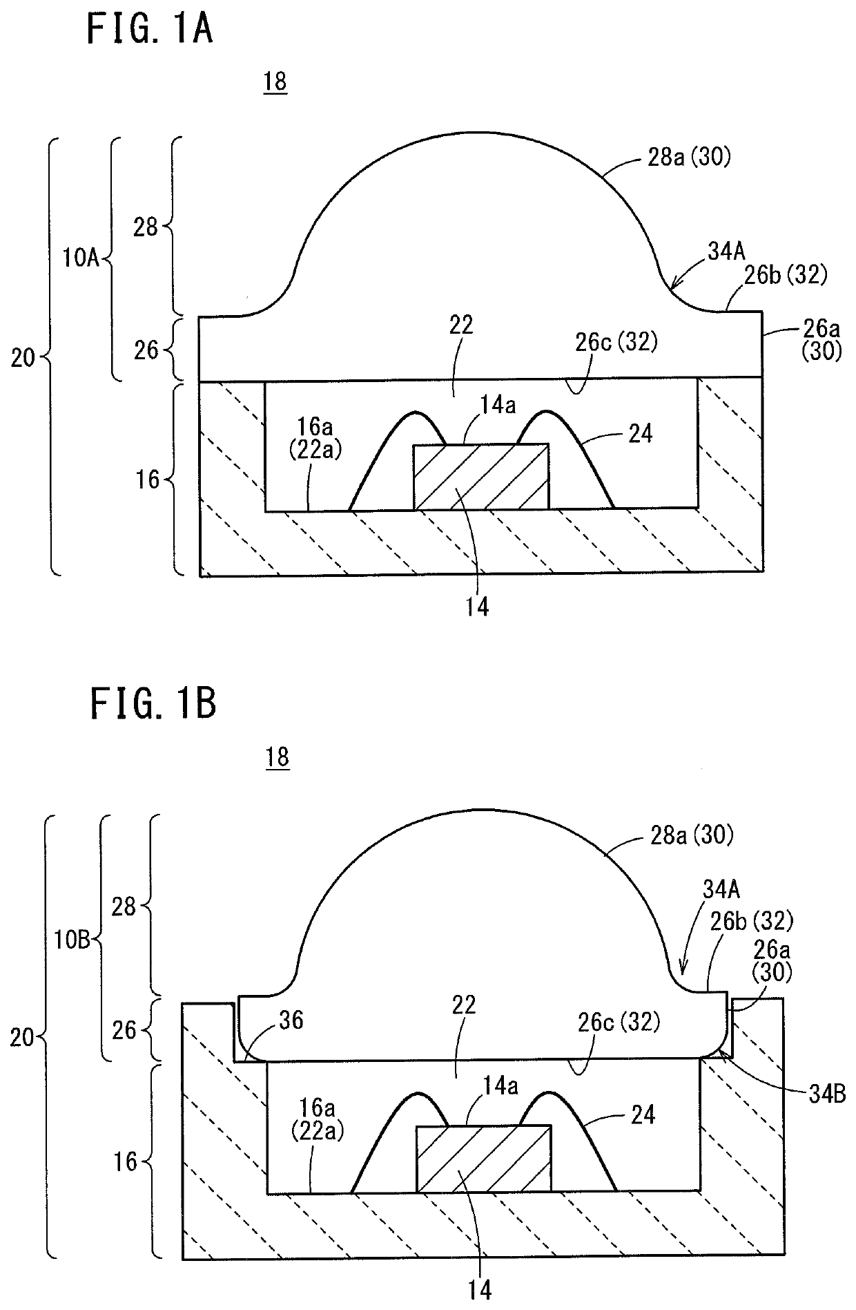
[0092]The transparent sealing member 10 according to Exemplary Embodiment 1 has a configuration similar to that of the first transparent sealing member 10A shown in FIG. 1A.

[0093]The method of manufacturing the transparent sealing member 10 according to Exemplary Embodiment 1 is as described below. More specifically, a slurry was prepared by mixing 100 parts by mass of a silica powder having an average particle diameter of 0.5 μm as a raw material powder, 2 parts by mass of a carboxylic acid copolymer as a dispersing agent, 49 parts by mass of dimethyl malonate as a dispersing medium, 4 parts by mass of ethylene glycol, 4 parts by mass of 4′4-diphenylmethane diisocyanate as a curing agent, and 0.4 parts by mass of triethylamine as a catalyst.

[0094]The slurry was poured into a metal mold at room temperature, and left at room temperature for a fixed time period. Subsequently, the molded body was released from the mold. Furthermore, the molded body was allowed to stand at room temperat...

exemplary embodiment 2

[0098]A silica powder molded body, which was manufactured by the same manufacturing method as in Exemplary Embodiment 1, was calcined at 500° C. in the atmosphere, and thereafter fired in a hydrogen atmosphere at a temperature 10° C. lower than in Exemplary Embodiment 1, thereby producing the transparent sealing member 10. Stated otherwise, the transparent sealing member 10 of Exemplary Embodiment 2 was manufactured by the same method as in Exemplary Embodiment 1, except that it was fired in the hydrogen atmosphere at a 10° C.-lower firing temperature. In Exemplary Embodiment 2, one hundred transparent sealing members 10, in which the radius of curvature of the curved shape formed in the first corner portion 34A was greater than or equal to 150 μm and less than 300 μm, were produced. Thereafter, one hundred optical components according to Exemplary Embodiment 2 were produced in the same manner as in Exemplary Embodiment 1.


PUM


Abstract

A first transparent sealing member is used in a package accommodating at least one optical element, and is attached to a mounting substrate having a mounting surface for the optical element. In the first transparent sealing member, at least one corner part among a plurality of corner parts configured by a surface facing the mounting substrate and a surface along the mounting surface of the mounting substrate has a curved shape, and punctiform minute recessed parts are formed on the surface of the curved shape. The average presence frequency of the minute recessed parts is 100,000 to 3,000,000 inclusive per 1 mm2.

Description

CROSS-REFERENCE TO RELATED APPLICATIONS[0001]This application is a Continuation of International Application No. PCT / JP2018 / 013303 filed on Mar. 29, 2018, which is based upon and claims the benefit of priority from International Application No. PCT / JP2017 / 023547 filed on Jun. 27, 2017, the contents all of which are incorporated herein by reference.TECHNICAL FIELD[0002]The present invention relates to a transparent sealing member which is used for optical components such as LEDs (light emitting diodes), LDs (semiconductor lasers), or the like, as well as to a method for manufacturing such a transparent sealing member.BACKGROUND ART[0003]Generally, with an optical component having an optical element (for example, an LED, an LD, or the like) that emits ultraviolet light, a transparent sealing member is required in order to protect the optical element from the open air and moisture. From the standpoints of permeability to ultraviolet rays and durability, glass or quartz glass is prefera...

Claims


Application Information

Patent Timeline
IPC IPC(8): H01L33/58H01L33/00H01L33/22H01L33/62H01L33/48
CPCH01L33/62H01L33/58H01L33/0095H01L33/22H01L33/483H01L33/54H01L2933/0058H01L2933/005H01L33/20H01L33/486
Inventor KIKUCHI, YOSHIOSHIBATA, HIROYUKI
Owner NGK INSULATORS LTD
Why Eureka
Try Eureka