
Heavy-duty pneumatic tire

Active Publication Date: 2009-05-21
BRIDGESTONE CORP
View PDF3 Cites 14 Cited by
  • Summary
  • Abstract
  • Description
  • Claims
  • Application Information

AI Technical Summary

Benefits of technology

[0022]The inventor conducted drum tests in order to evaluate the running durability of conventional tires including a main belt as shown in the half-width sectional view of FIG. 10, which is taken in the tire width direction. As a result, it has been clarified that, with respect to two narrow belt layers 52, 53 on the inner layer side, which are arranged on the outer peripheral side of the crown region of a radial carcass 51, there are generated at the side edges of the narrow belt layer 53 on the outer layer side, cracks C1 extending toward the narrow belt layer 52 on its inner layer side, and also cracks C2 extending toward a wide belt layer 54 arranged on the outer layer side adjacent to the narrow belt layer 53 on its outer peripheral side, and growing between the belt layers 53, 54. It has also been clarified that there are generated at the side edges of the innermost belt layer 52, cracks C3 extending toward the narrow belt layer 53 on its outer peripheral side and growing between the belt layers 52, 53. Incidentally, reference numeral 55 denotes the outermost wide belt layer arranged on the outer layer side.
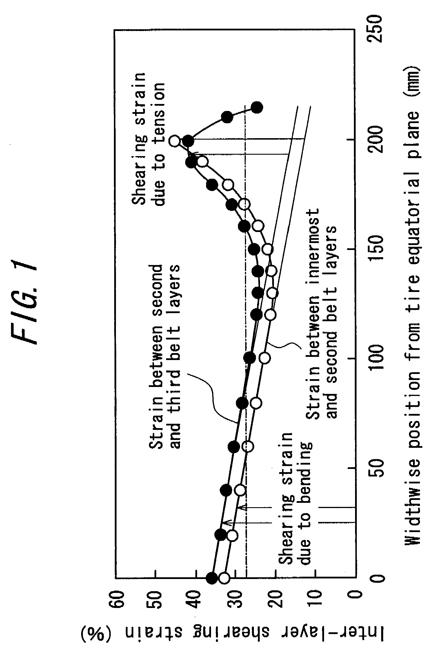
[0023]Then, the occurrence situation of interlayer shearing strain, which causes generation of such cracks C1, C2 and C3, has been analyzed by means of strain analysis with finite element method. Such analysis revealed that the interlayer shearing strain can be classified as a first type of interlayer shearing strain that occurs over the entire width of the belt due to a bending deformation of the belt in a widthwise-sectional plane of the tire, which, in turn, occurs as a result of the compressive deformation of the ground contact portion of the tread during the running of the tire under a loaded condition, and as a second type of interlayer shearing strain due to a circumferential tensile force generated at the side portion of the belt when the tire is loaded or when lateral forces are applied to the tread surface.
[0024]Therefore, it can be concluded that the cracks C1, C2 and C3 from the side edges of the belt layers 52, 53 as explained above are generated as a result of superimposition of such two types of interlayer shearing strains, the mode of which can be exemplarily illustrated by a graph as shown in FIG. 11. It is to be noted that the shearing strain (%) for the ordinate of this graph refers to the strain rate between the belt layers that undergo dislocation in the circumferential direction.
[0025]It can be understood from FIG. 11 that the strain between the narrow belt layers 52, 53 is noticeably high at the side edges as a result of superimposition of the shearing strain due to the bending and the shearing strain due to tension. On the other hand, the strain between the belt layers 53, 54 is high at the side edges of the narrow belt layers 52, 53 similar to the strain therebetween, but gradually decreases from the side edge of the narrow belt layer 53 toward the outer side in the width direction of the tire.
[0026]In view of the above, in order to suppress occurrence of cracks C1, C2 and C3, it is effective to reduce at least one of the shearing strain due to the bending and the shearing strain due to tension.
[0027]Here, in order to reduce the shearing strain due to the bending deformation, it is effective to make large the difference in circumferential elongation between the neighboring belt layers so that the bending deformation upon stepping-in and kicking-out of the tread surface is absorbed by the elongation of the belt layers, per se, instead of elongation of the interlayer rubber of the belt layers. It is also important to take a large distance between the belt layers on the inner layer side and the belt layers on the outer layer side. Thus, in order to suppress the strain at the side edges of the second-innermost narrow belt layer subjected to severe concentration of the shearing strain, for example, it is effective for the wide belt layer as the third belt layer, and also for the wide belt layer as the fourth belt layer, if any, to be convex radially outwards, at locations corresponding to the side edges of the narrow belt layer as the second belt layer. However, the resultant increase in the interlayer distance gives rise to problems of increased total thickness of the tread portion and increased heat generation quantity during the rolling of the tire, thereby degrading the thermal durability of the tire.

Problems solved by technology

Such strain tend to become large when the belt cords have an small intersection angle relative to the tire equatorial plane and the belt layers have large widths, as in the case of the above-mentioned narrow belt layers on the inner layer side, thereby giving rise to problems of a premature formation of cracks at locations of increased strain in the side edges of the belt layers, and the tendency of an interlayer growth of such cracks.
This is incompatible with the requirement for a reduced width of the narrow belt layers in order to reduce the strain at the side edges of the belt layers.
Thus, for example, if priority is given to the strain reduction and the width of the narrow belt layers is thus reduced, then problems are caused in that the diametrical growth of the tire during rolling under a loaded condition cannot be avoided, with inevitable increase in heat generation quantity and wear amount, beside that the so-called “cut separation” tends to occur wherein the tread rubber undergoes separation due to premature growth, along the outer surface of the outermost belt layer, of the cuts occurring in the tread surface, etc.

Method used


Image

  • Heavy-duty pneumatic tire
  • Heavy-duty pneumatic tire
  • Heavy-duty pneumatic tire

Examples


example 1

[0083]There have been prepared test tires having a size of 4000R57, and six-layered belt structure and tread width as shown in FIG. 6, wherein the maximum projection height positions of the projections are situated at 78% positions on both sides of the tire equatorial plane X. The maximum projection height C of these projections were varied as shown in FIGS. 7(a) to 7(d) to evaluate the durability of the belt, and the results as shown in FIG. 8 were obtained. Incidentally, the diameter of the belt cords of the innermost belt layer was 2.5 mm.

[0084]Here, the evaluation was performed by mounting the test tires to a rim having a rim width of 29 inches, setting the inflation inner pressure as 700 Pa, and subjecting the test tires under loaded condition to rolling on a test drum having a diameter of 5.0 m, under the temperature of 30° C. and at a speed of 10 km / h. In this instance, the load weight was 150% of the weight as prescribed by TRA standards, and the lateral force applied to the...

example 2

[0089]Test tires were prepared to have the same basic structure as the test tires used in Example 1, wherein the maximum projection height of the innermost narrow belt layer 1B is 3 mm (=1.2×d1), and the third wide belt layer 3B is provided with projections 10 at locations corresponding to the side edges of the narrow belt layer 1B, 2B so as to be convex radially outwards, as shown FIG. 9. For these test tires, the durability of the belt was evaluated in the manner similar to Example 1. It has been revealed, as symbolically shown by circles (∘) and squares (□) in the graph of FIG. 8, that C12 and C23 could be reduced to 28 mm and 30 mm, respectively, and both CC12 and CC23 could be reduced to 0 mm.

[0090]Namely, this is based on the fact that, due to the provision of the projections 10 for the wide belt layer 3B, the side portions of that belt layer 3B have increased regions that are included in the compression side, making it possible to increase the difference in elongation / contrac...


PUM

PropertyMeasurementUnit
Angleaaaaaaaaaa
Angleaaaaaaaaaa
Angleaaaaaaaaaa

Abstract

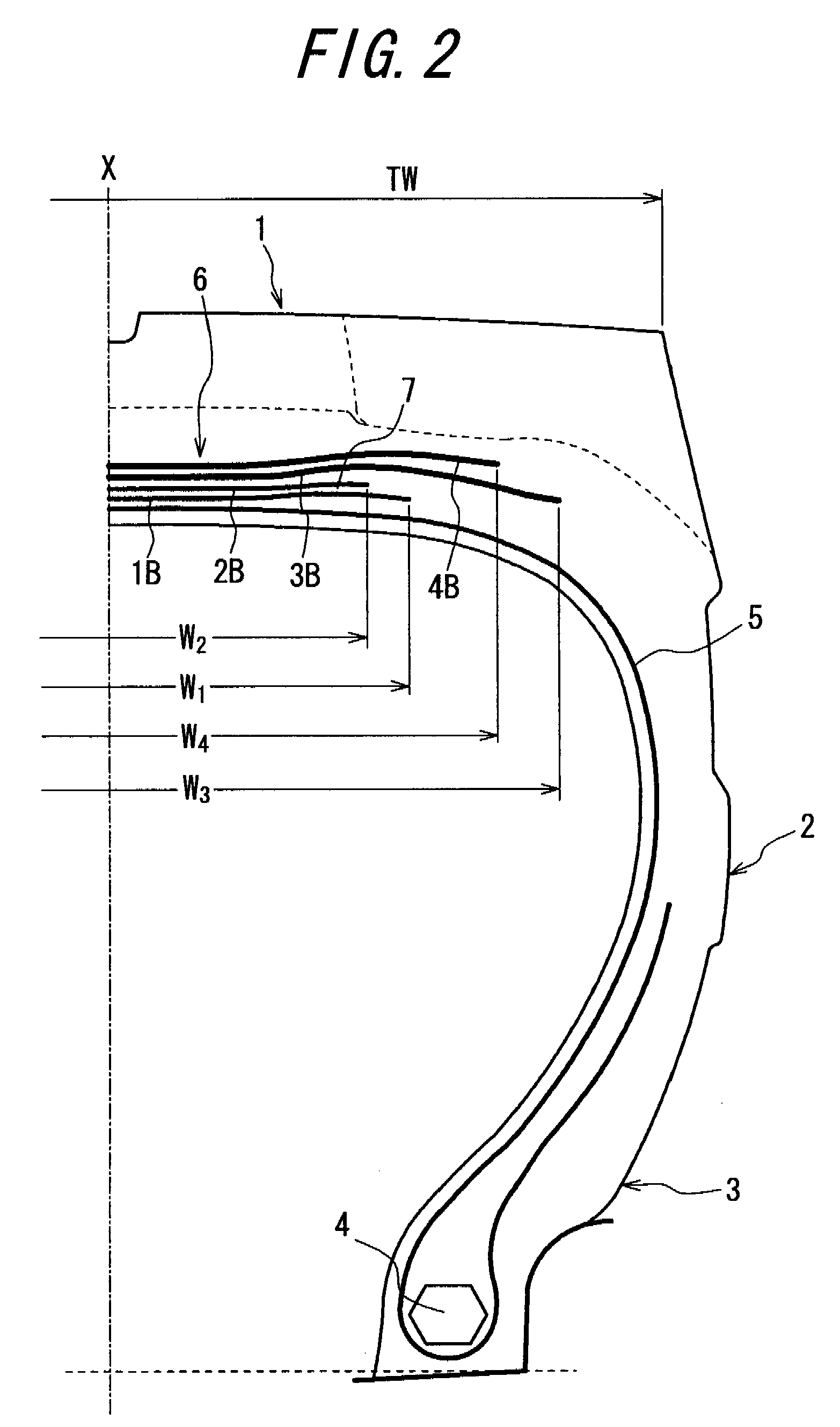
A heavy-duty pneumatic tire capable of sufficiently suppressing the amount of strain occurring in side edges of a belt layer is sufficiently suppressed, despite the required increase in width of the narrow belt layers on the inner layer side, so as to effectively prevent separation of the belt layer and, hence, separation of the belt. The tire includes two narrow belt layers (1B, 2B) on the inner layer side, and two wide belt layers (3B, 4B) on the outer layer side, which are larger in width than the narrow belt layers. The narrow belt layers and the wide belt layers are sequentially arranged on the outer circumferential side of a crown region of a radial carcass (5). The innermost narrow belt layer (1B) has side edges that are convex radially outwards.

Description

CROSS REFERENCE TO RELATED APPLICATION[0001]This application is a National Stage of International Application No. PCT / JP2006 / 310360 filed on May 24, 2006, claiming priority based on Japanese Patent Application No. 2005-209884, filed Jul. 20, 2005, the contents of all of which are incorporated herein by reference in their entirety.TECHNICAL FIELD[0002]The present invention relates to a heavy-duty radial tire, which can be suitably used as truck / bus tires, construction vehicle tires, etc., as being inflated under high pneumatic pressure and used under high load conditions. More specifically, the present invention provides a technology that serves to effectively prevent separation of a belt layer comprised of not less than three plies of belt layers, at its side edge positions and thereby improve the durability of the belt.BACKGROUND AR[0003]With respect to this type of conventional tires, for example, JP2000-225810A (or corresponding U.S. Pat. No. 6,578,611B2) discloses a tire includi...

Claims


Application Information

Patent Timeline
IPC IPC(8): B60C9/28B60C9/18
CPCB60C9/2006B60C9/28Y10T152/10765Y10T152/10801B60C2200/06B60C2009/1842
Inventor KOBAYASHI, KAZUOMI
Owner BRIDGESTONE CORP
Learn More