
Slit lamp microscope and ophthalmic system

Pending Publication Date: 2021-05-27
KK TOPCON
View PDF0 Cites 0 Cited by
  • Summary
  • Abstract
  • Description
  • Claims
  • Application Information

AI Technical Summary

Benefits of technology

The patent provides a way to provide high-quality slit lamp microscope examinations.

Problems solved by technology

However, acquisition of an adequate images using a slit lamp microscope requires fine and complicated operations such as illumination angle adjustment and photographing angle adjustment.
This causes problems such as the duration of examination becoming long, and being unable to obtain an adequate image.
In addition, while slit lamp microscopes are effective for screening and other examinations as described above, the current situation is that there is a shortage of persons who have expertise in this equipment, and it is not possible to provide high quality examinations to many people.

Method used


Image

  • Slit lamp microscope and ophthalmic system
  • Slit lamp microscope and ophthalmic system
  • Slit lamp microscope and ophthalmic system

Examples


first embodiment example

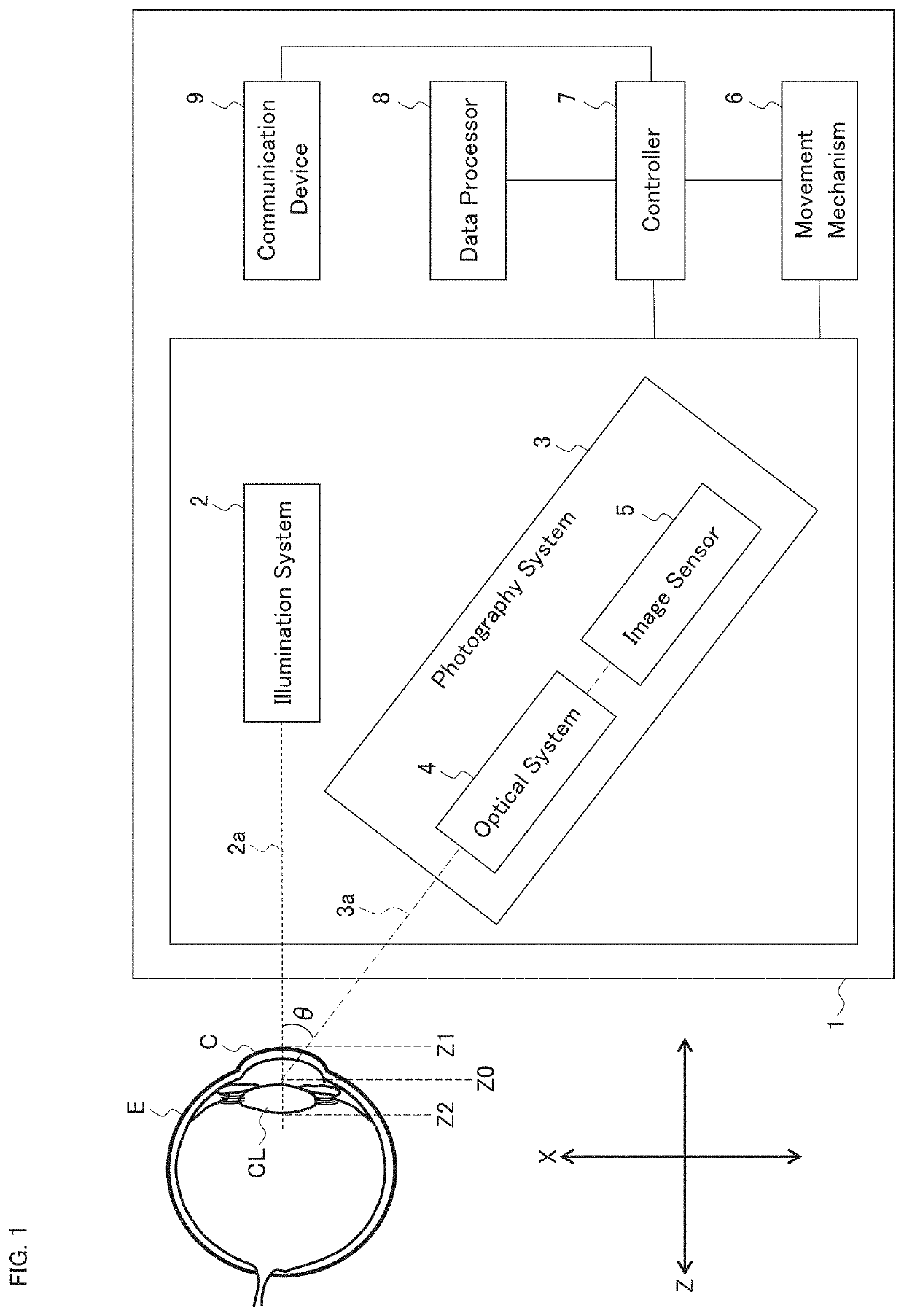
[0109]FIG. 1 shows an example of the slit lamp microscope according to the first embodiment example.

[0110]The slit lamp microscope 1 may be used for photographing the anterior segment of the subject's eye E, and includes the illumination system 2, the photography system 3, the movement mechanism 6, the controller 7, the data processor 8, and the communication device 9. The cornea of the subject's eye E is denoted by the reference character C, and the crystalline lens is denoted by the reference character CL.

[0111]The slit lamp microscope 1 may be a single apparatus, or may also be a system that includes two or more apparatuses. In the case where the slit lamp microscope 1 is configured as a system, the slit lamp microscope 1 may include a main apparatus, a computer, and a communication device. Here, the main apparatus may include the illumination system 2, the photography system 3, and the movement mechanism 6, the computer may include the controller 7, the data processor 8, and the...

second embodiment example

[0190]The present embodiment example describes a configuration of an optical system applicable to the slit lamp microscope 1 of the first embodiment example. An example thereof is shown in FIG. 5. In addition to the elements shown in FIG. 5, the slit lamp microscope 1 of the present embodiment example may further be provided with any of the elements shown in other embodiment examples. For example, the controller 7, the data processor 8, the communication device 9, etc. of the first embodiment example may be provided.

[0191]The illumination system 20 shown in FIG. 5 is an example of the illumination system 2 of the first embodiment example, and the pair of the left photography system 30L and the right photography system 30R is an example of the photography system 3. The reference character 20a denotes the optical axis of the illumination system 20 (referred to as the illumination optical axis), the reference character 30La denotes the optical axis of the left photography system 30L (r...

third embodiment example

[0222]The present embodiment example will describe a configuration example of the processing system applicable to the slit lamp microscope 1 of the first embodiment example. As shown in FIG. 5 described in the second embodiment example, for example, the photography system 3 of the present embodiment example may be configured in such a manner that the left photography optical axis 30La and the right photography optical axis 30Ra are tilted in mutually opposite directions with respect to the illumination optical axis 20a. The processing system of the present embodiment example is configured to execute the processing related to an artifact as described below.

[0223]The data processor 8A shown in FIG. 7 is an example of the data processor 8 of the first embodiment example. The data processor 8A includes the image selecting processor 81.

[0224]The image selecting processor 81 is configured to judge whether an artifact is contained in at least one of two images that are substantially simult...


PUM


Abstract

A slit lamp microscope of some embodiment examples includes an illumination system, photography system, and movement mechanism. The illumination system projects slit light onto an anterior segment of an eye. The photography system includes an optical system and image sensor. The optical system directs light coming from the anterior segment onto which the slit light is being projected. The image sensor includes a light detecting plane that receives the light directed by the optical system. The movement mechanism moves the illumination and photography systems. The subject plane along the optical axis of the illumination system, the optical system, and the light detecting plane satisfy the Scheimpflug condition. The photography system acquires a plurality of images of the anterior segment by performing repetitive photography in parallel with movement of the illumination and photography systems performed by the movement mechanism.

Description

FIELD[0001]The present disclosure relates to a slit lamp microscope and an ophthalmic system.BACKGROUND[0002]Diagnostic imaging serves an important role in the field of ophthalmology. Diagnostic imaging uses various kinds of ophthalmic imaging apparatuses. Examples of ophthalmic imaging apparatuses include a slit lamp microscope, a fundus camera, a scanning laser ophthalmoscope (SLO), an optical coherence tomography (OCT) apparatus, and the like. In addition, various kinds of ophthalmic examination apparatuses and ophthalmic measurement apparatuses, such as a refractometer, a keratometer, a tonometer, a specular microscope, a wave front analyzer, and a micro perimeter, are equipped with the function of imaging anterior eye segment, eye fundus, etc.[0003]A slit lamp microscope is one of the most widely and frequently utilized apparatuses among various kinds of ophthalmic apparatuses. A slit lamp microscope is an ophthalmic apparatus for illuminating a subject's eye with slit light an...

Claims


Application Information

Patent Timeline
IPC IPC(8): A61B3/135A61B3/00A61B3/14
CPCA61B3/135A61B3/14A61B3/0008A61B3/12A61B3/024
Inventor OOMORI, KAZUHIROFUKUMA, YASUFUMISHIMIZU, HITOSHI
Owner KK TOPCON
Features
  • Generate Ideas
  • Intellectual Property
  • Life Sciences
  • Materials
  • Tech Scout
  • Unparalleled Data Quality
  • Higher Quality Content
  • 60% Fewer Hallucinations
Learn More